Honda HR-V: Component Location Index
Honda HR-V (2015-2021) Service Manual / Transmission / Continuously Variable Transmission (CVT) - Testing & Troubleshooting / Component Location Index
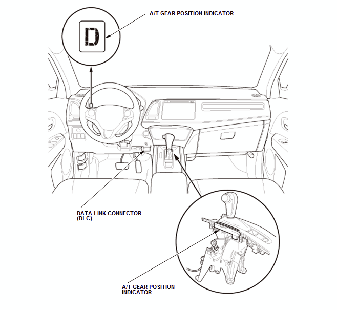
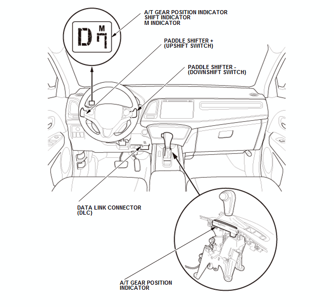
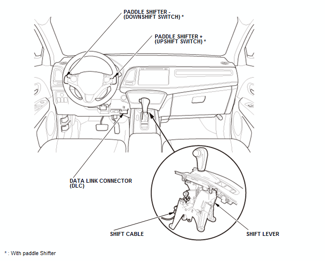
A/T GEAR POSITION INDICATOR COMPONENT LOCATION INDEX (CVT)
Without paddle shifter
With paddle shifter
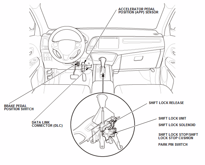
A/T INTERLOCK SYSTEM COMPONENT LOCATION INDEX (CVT)
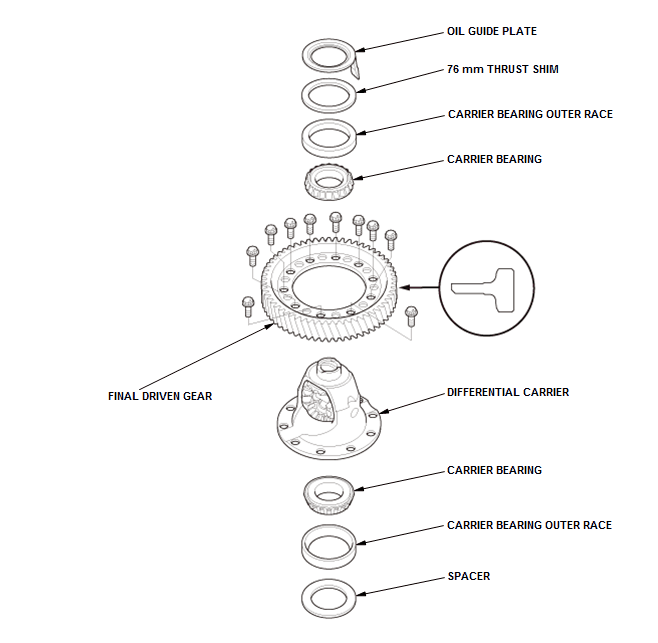
CVT DIFFERENTIAL COMPONENT LOCATION INDEX (CVT)
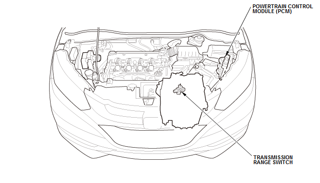
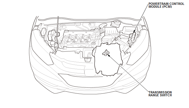
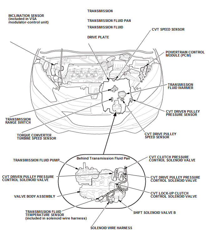
CVT SYSTEM COMPONENT LOCATION INDEX (CVT)
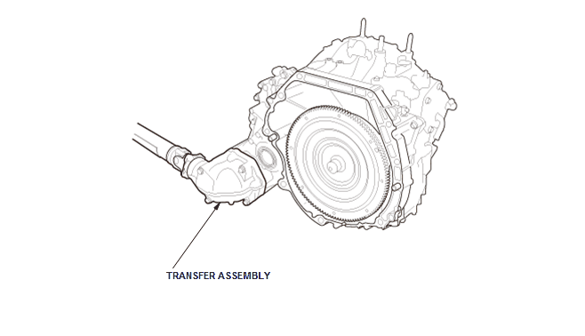
TRANSFER ASSEMBLY COMPONENT LOCATION INDEX (CVT)
READ NEXT:
 How to Information
HOW TO TROUBLESHOOT THE CVT SYSTEM (CVT)
How to Check for DTCs with the Honda Diagnostic System (HDS)
When the powertrain control module (PCM) senses an abnormality in the input
or output systems, th
Manual Transaxle - Service Information
Back-Up Light Switch Removal and Installation (M/T)
Removal
1. Air Cleaner - Remove
2. Back-Up Light Switch - Removal
Disconnect the connector (A)
Remove the back-up light switch (B).
Installatio
SEE MORE:
Rearview Camera Image Does Not Come ON Or Work Properly (Without Navigation,
Color Audio Type (5-inch Screen) )
NOTE:
Check the vehicle 12 volt battery condition first.
Check the connectors for poor connections or loose terminals.
1. Problem verification:
Turn the vehicle to the ON mode.
Shift the transmission to R position/mode.
Does the audio display image change when the transmission is shifted to
Immobilizer System Symptom Troubleshooting Information
General Check Before Troubleshooting
Before troubleshooting the immobilizer system, check the following general
items and resolve any issues, if
applicable:
The 12 volt battery is low; charge the 12 volt battery fully, then
troubleshoot the immobilizer system.
The ignition key is not a genuine
© 2019-2026 Copyright www.hohrv2.com
