Honda HR-V: How to Information
HOW TO TROUBLESHOOT THE CVT SYSTEM (CVT)
How to Check for DTCs with the Honda Diagnostic System (HDS)
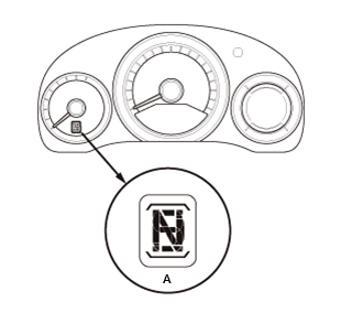
When the powertrain control module (PCM) senses an abnormality in the input or output systems, the A/T gear position indicator (A) in the gauge control module will usually blink as shown.
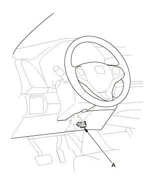
When the Honda Diagnostic System (HDS) is connected to the data link connector (DLC) (A) located under the driver's side of the dashboard, and when turn the vehicle to the ON mode, and the appropriate menu is selected, it will indicate the diagnostic trouble code (DTC).
If the A/T gear position indicator or the malfunction indicator lamp (MIL) has been reported on, or if a driveability problem is suspected, follow this procedure:
1. Connect the HDS to the DLC. (See the HDS user's manual for specific instructions.)
2. Turn the vehicle to the ON mode.
3. Make sure the HDS communicates with the vehicle. If it does not, go to the DLC circuit troubleshooting.
4. Check for Pending or Confirmed DTCs with the HDS.
5. Record the freeze data and the on-board snapshots for all fuel and emissions DTCs and A/T DTCs.
6. If there is a fuel and emissions DTC, first check the fuel and emissions system as indicated by the DTC.
7. Clear the DTC and the data.
8. Drive the vehicle for several minutes under the same conditions as those indicated by the freeze data, and then recheck for a DTC.
If the A/T DTC returns, go to the indicated DTC's troubleshooting. If the DTC does not return, there was an intermittent problem within the circuit. Make sure all pins and terminals in the circuit are tight.
Symptom Troubleshooting Versus DTC Troubleshooting
Some symptoms will not set DTCs or cause the A/T gear position indicator to blink. If the MIL was reported ON or the A/T gear position indicator has been blinking, check for DTCs. If the vehicle has an abnormal symptom, and there are no DTCs stored, do the symptom troubleshooting. Check the list of probable cause(s) for the symptom, in the sequence listed, until you find the problem.
How to Troubleshoot Circuits at the PCM Connectors
NOTE: The PCM stays on for up to an hour after the vehicle is turned to the OFF (LOCK) mode. Jumping the SCS line after turning the vehicle to select the OFF (LOCK) mode cancels this function. Disconnecting the PCM during this function, without jumping the SCS line first, can damage the PCM.
1. Jump the SCS line with the HDS
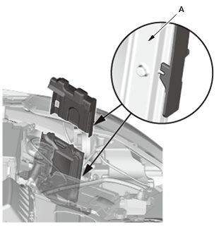
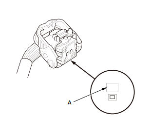
2. Remove the PCM cover (A).
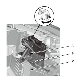
3. Disconnect PCM connectors A, B, and C.
NOTE: PCM connectors A, B, and C have symbols (A=□, B=Δ, C=◦) embossed on them for identification.
4. When diagnosis/troubleshooting is done at the PCM connectors, use the terminal test port (A) above the terminal you need to check.
5. Connect one side of the patch cord terminals (A) to a commercially available digital multimeter (B), and connect the other side of the terminal (C) to a commercially available banana jack (Pomona Electronics Tool No. 3563 or equivalent) (D).
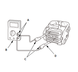
6. Gently contact the pin probe (male) at the terminal test port from the terminal side. Do not force the tips into the terminals.

- For accurate results, always use the pin probe (male).
- To prevent damage to the connector terminals, do not insert test equipment probes, paper clips, or other substitutes as they can damage the terminals. Damaged terminals cause a poor connection and an incorrect measurement.
- Do not puncture the insulation on a wire. Punctures can cause or eventually lead to poor or intermittent electrical connections.
Clear A/T DTCs Procedure
1. Connect the HDS to the DLC (A) located under the driver's side of the dashboard.

2. Turn the vehicle to the ON mode.
3. Make sure the HDS communicates with the vehicle. If it does not, go to the DLC circuit troubleshooting.
4. Clear the DTC(s) with the HDS.
OBD Status
The OBD status shows the current system status of each DTC and all of the parameters. This function is used to see if a repair was successfully completed. The results of diagnostic tests for the DTC are displayed as:
- PASSED: The on-board diagnosis is successfully completed.
- FAILED: The on-board diagnosis has finished but failed.
- NOT COMPLETED: The on-board diagnosis was running but is out of the enable conditions of the DTC.
How to End a Troubleshooting Session (required after any troubleshooting)
NOTE: Reset the PCM with the HDS while the engine is stopped.
1. Turn the vehicle to the OFF (LOCK) mode
2. Turn the vehicle to the ON mode, and wait for 30 seconds
3. Turn the vehicle to the OFF (LOCK) mode, and disconnect the HDS from the DLC
4. Start the engine with the shift lever in P or N position/mode, and warm it up to normal operating temperature (the radiator fan comes on twice)
5. To verify that the problem is repaired, test-drive the vehicle for several minutes at speeds over 31 mph (50 km/h) or under the same conditions as those indicated by the freeze data.
Failure Reproduction Technique
NOTE: Follow these points while the vehicle is raised on a lift for the test-drive
- In case of the vehicle speed below 31 mph (50 km/h): Disable the VSA by pressing the VSA OFF button.
- In case of the vehicle speed above 31 mph (50 km/h): Enter the VSA maintenance mode.
- VSA DTC(s) may come on when test-driving on a lift. If the VSA DTC(s) come on, clear the DTC(s) with the HDS.
- Use the S-paddle shift mode to select gears manually for model equipped with the paddle shifters.
Self-Diagnosis
If the PCM detects the failure of a signal from a sensor, a switch, a solenoid valve, or from another control unit, it stores a Pending or Confirmed DTC. Depending on the failure, a DTC is stored in either the first or the second drive cycle. When a Confirmed DTC is stored, the PCM blinks the A/T gear position indicator and/or turns on the malfunction indicator lamp (MIL) by a signal sent to the gauge control module via F-CAN.
- One Drive Cycle Detection Method: When an abnormality occurs in the signal from a sensor, a switch, a solenoid valve, or from another control unit, the PCM stores a Pending or Confirmed DTC for the failure and blinks the A/T gear position indicator and/or turns on the MIL immediately.
- Two Drive Cycle Detection Method: When an abnormality occurs in the signal from a sensor, a switch, a solenoid valve, or from another control unit in the first drive cycle, the PCM stores a Pending DTC. The A/T gear position indicator and the MIL do not turns on at this time. If the failure continues in the second drive cycle, the PCM stores a Confirmed DTC and blinks the A/T gear position indicator and/or turns on the MIL.
Fail-Safe Function
When an abnormality occurs in the signal from a sensor, a switch, a solenoid valve, or from another control unit, the PCM ignores that signal and substitutes a pre-programmed value for that signal to allow the CVT to continue operating. This causes a DTC to be stored and the A/T gear position indicator to blink and/or the MIL to come on. The transmission may not shift normally during failsafe operation. Do not run the test-driving diagnosis when the MIL is ON, or the A/T gear position indicator is blinking.
READ NEXT:
 Manual Transaxle - Service Information
Back-Up Light Switch Removal and Installation (M/T)
Removal
1. Air Cleaner - Remove
2. Back-Up Light Switch - Removal
Disconnect the connector (A)
Remove the back-up light switch (B).
Installatio
SEE MORE:
Shift Lock System Circuit Troubleshooting (CVT)
NOTE: Check for PGM-FI DTCs and CVT DTCs. If any DTCs are present,
troubleshoot those first.
PGM-FI System
CVT System
1. Shift lock solenoid check:
Connect the HDS to the DLC - Refer to: How to Troubleshoot the Fuel and
Emissions Systems, or How to Troubleshoot the CVT System (CVT).
Turn the
Wheel Bolt Removal and Installation
Special Tools Required
Ball Joint Remover, 28 mm 07MAC-SL00202
Removal
Do not use a hammer or impact tools (pneumatic or electric).
Be careful not to damage the threads of the wheel bolts.
Front
1. Vehicle - Lift
2. Front Wheel - Remove
3. Front Hub - Remove
4. Wheel Bolt - Remove
Separate
