Honda HR-V: A/F Sensor Removal and Installation
Honda HR-V (2015-2021) Service Manual / Engine / Engine Control System & Engine Mechanical - Service Information / A/F Sensor Removal and Installation
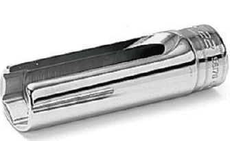
Special Tools Required
O2 Sensor Wrench Snap-on S6176 or equivalent, commercially available
Removal & Installation
1. A/F Sensor - Remove
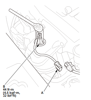
Fig. 1: A/F Sensor With Torque Specification
- Disconnect the connector (A)
- Remove the A/F sensor (B).
2. All Removed Parts - Install
- Install the parts in the reverse order of removal.
ACCELERATOR PEDAL MODULE REMOVAL AND INSTALLATION
Removal & Installation
1. Accelerator Pedal Module - Remove
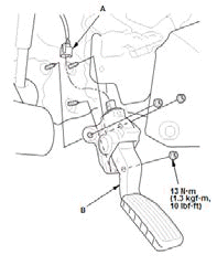
- Disconnect the connector (A)
- Remove the accelerator pedal module (B).NOTE : The APP sensor is not available separately. Do not disassemble the accelerator pedal module.
2. All Removed Parts - Install
- Install the parts in the reverse order of removal.
READ NEXT:
 Air Cleaner Element Removal, Installation, and Inspection
Removal & Installation
1. Air Cleaner Element - Remove
Removal & Installation
Air Cleaner Element - Remove
2. All Removed Parts - Install
Install the parts in the reverse order of remov
CKP Sensor Removal and Installation
Removal & Installation
1. Engine Undercover (2WD) - Remove
2. CKP Sensor Cover - Remove
Remove the CKP sensor cover (A).
3. CKP Sensor - Remove
4. All Removed Parts - Install
Install the pa
Camshaft Removal and Installation
Removal & Installation
1. PCM and Bracket - Remove
2. Air Cleaner - Remove
3. Intake Air Duct - Remove
4. Positive Cable and Connector (Alternator) - Disconnect
NOTE: Remove the positive cable cla
SEE MORE:
Keyless Access System Description - Components
LF (Low Frequency) Antennas
The front interior, rear interior, driver's door, and front passenger's door
LF antennas send the signals to the
remote inside and outside of the vehicle.
Door Touch Sensors and Outer Handle Lock Switches, Tailgate Outer Handle
Switch and Lock Switch
The door touch sens
Engine Assembly Torque Rod Removal and Installation
Removal & Installation
1. Engine Undercover - Remove (With Engine Undercover)
2. Engine - Support
Lift and support the engine with a transmission jack and a wood block
under the oil pan.
3. Torque Rod - Remove
2WD
AWD
NOTE: When install the torque rod, be sure to install the torque rod wi
© 2019-2026 Copyright www.hohrv2.com
