Honda HR-V: CKP Sensor Removal and Installation
Removal & Installation
1. Engine Undercover (2WD) - Remove
2. CKP Sensor Cover - Remove
.png)
- Remove the CKP sensor cover (A).
3. CKP Sensor - Remove
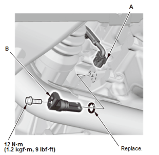
4. All Removed Parts - Install
- Install the parts in the reverse order of removal with a new O-ring.
5. CKP Pattern - Clear/Learn
CMP SENSOR REMOVAL AND INSTALLATION
Removal & Installation
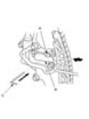
1. CMP Sensor - Remove
.png)
- Disconnect the connector (A)
- Remove the CMP sensor (B).
2. All Removed Parts - Install
- Install the parts in the reverse order of removal with a new O-ring.
3. CKP Pattern - Clear/Learn
CAM CHAIN AUTO-TENSIONER REMOVAL AND INSTALLATION
Removal
1. Right Front Wheel - Remove
2. Right Front Splash Shield - Remove
3. Drive Belt - Remove
4. Cain Case Cover - Remove
.png)
5. Cam Chain Auto-Tensioner - Remove
.png)
- Turn the crankshaft counterclockwise to compress the cam chain auto-tensioner.
- Rotate the crankshaft counterclockwise to align the holes on the lock
(A) and the cam chain
auto-tensioner (B), then insert a 1.0 mm (1/32 in) diameter pin (C) into the
holes. Turn the
crankshaft clockwise about 90º to secure the pin.
NOTE: If the holes in the lock and the cam chain auto-tensioner do not align, continue to rotating the crankshaft counterclockwise until the holes align, then install the pin.
- Remove the cam chain auto-tensioner.
Installation
1. Cam Chain Auto-Tensioner - Install
.png)
- Compress the cam chain auto-tensioner when replacing the cam chain.
Remove the pin (A)
from the cam chain auto-tensioner that was installed during removal. Turn
the plate (B)
counterclockwise, to release the lock, then press the rod (C), and set the
first cam (D) to the first
edge of the rack (E). Insert the 1.0 mm (1/32 in) diameter pin back into the
holes (F).
NOTE: If the cam chain auto-tensioner is not set up as described, the cam chain auto-tensioner will be damaged.
- Install the cam chain auto-tensioner.
.png)
- Remove the pin.
2. Cain Case Cover - Install
.png)
- Apply liquid gasket to the oil pump mating surface of the chain case cover, and to the inside edge of the threaded bolt holes.
- Install the chain case cover.
3. Drive Belt - Install
4. Right Front Splash Shield - Install
5. Right Front Wheel - Install
CAM CHAIN REMOVAL AND INSTALLATION
Removal
NOTE: Keep the cam chain away from magnetic fields.
1. Camshaft Timing - Inspect
2. Oil Pump - Remove
3. Cam Chain - Inspect
.png)
- Measure the tensioner rod length between the tensioner body and bottom of the flat surface section on the tensioner rod. If the length is more than the service limit, replace the cam chain.
Tensioner Rod Length
Service Limit: 14.5 mm (0.571 in)
4. Cam Chain Auto-Tensioner - Remove
.png)
- Loosely install the crankshaft pulley
- Turn the crankshaft counterclockwise to compress the cam chain auto-tensioner.
.png)
- Rotate the crankshaft counterclockwise to align the holes on the lock (A) and the cam chain auto-tensioner (B)
- Insert a 1.0 mm (1/32 in) diameter pin (C) into the holes
- Turn the crankshaft clockwise to secure the pin.
NOTE : If the holes in the lock and the cam chain auto-tensioner do not align, continue to rotating the crankshaft counterclockwise until the holes align, then install the pin.
.png)
- Remove the cam chain auto-tensioner
- Remove the crankshaft pulley.
5. Cam Chain - Remove
.png)
- Remove the cam chain guide (A) and the cam chain tensioner arm (B)
- Remove the cam chain.
Installation
NOTE: Keep the cam chain away from magnetic fields.
1. No. 1 Piston at Top Dead Center - Set
.png)
- Set the crankshaft to top dead center (TDC). Align the TDC mark (A) on the crankshaft sprocket with the pointer (B) on the engine block.
.png)
- Set the camshaft to TDC. The "UP" mark (A) on the camshaft sprocket should be at the top, and the TDC grooves (B) on the camshaft sprocket should aline up with the top edge of the cylinder head.
2. Cam Chain - Install
.png)
- Install the cam chain on the crankshaft sprocket with the colored piece (A) aligned with the mark (B) on the crankshaft sprocket.
.png)
- Install the cam chain on the camshaft sprocket with the colored link plate (A) aligned with the mark (B) on the camshaft sprocket.
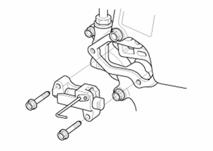
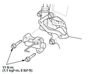
3. Cam Chain Guide and Cam Chain Tensioner Arm - Install
.png)
Fig. 2: Cam Chain Guide With Torque Specifications
4. Cam Chain Auto-Tensioner - Install
.png)
- Compress the cam chain auto-tensioner when replacing the cam chain.
Remove the pin (A)
from the cam chain auto-tensioner that was installed during removal. Turn
the plate (B)
counterclockwise, to release the lock, then press the rod (C), and set the
first cam (D) to the first
edge of the rack (E). Insert the 1.0 mm (1/32 in) diameter pin back into the
holes (F).
NOTE: If the cam chain auto-tensioner is not set up as described, the cam chain auto-tensioner will be damaged.
.png)
- Install the cam chain auto-tensioner.
.png)
- Remove the pin.
5. Oil Pump - Install
READ NEXT:
 Camshaft Removal and Installation
Removal & Installation
1. PCM and Bracket - Remove
2. Air Cleaner - Remove
3. Intake Air Duct - Remove
4. Positive Cable and Connector (Alternator) - Disconnect
NOTE: Remove the positive cable cla
Connecting Rod Bearing Replacement
Replacement
1. Engine/Transmission - Remove
2. Transmission - Remove
Remove the transmission:
M/T
CVT
3. Pressure Plate, Clutch Disc, and Flywheel - Remove (M/T)
4. Drive Plate - Remove (CV
Crankshaft Main Bearing Replacement
Replacement
1. Engine/Transmission - Remove
2. Transmission - Remove
Remove the transmission:
M/T
CVT
3. Pressure Plate, Clutch Disc, and Flywheel - Remove (M/T)
4. Drive Plate - Remove (CV
SEE MORE:
CVT Differential Oil Seal Replacement (CVT)
Special Tools Required
Driver Handle, 15 x 135L 07749-0010000
Oil Seal Driver, 65 mm 07JAD-PL90100
Oil Seal Driver Attachment, 58 mm
07JAD-PH80101
Replacement
NOTE: Apply a light coat of clean transmission fluid on all parts before
installation.
Transmission Housing Side
1. Differential Oil Seal
Rear Differential Clutch Test (AWD)
Test
1. HDS - Connect
2. Rear Differential Clutch - Test
Block the front wheels (A), raise the left rear wheel, and support it
with a safety stand (B) as shown
Release the parking brake.
Hold the left rear tire, and turn it counterclockwise continuously for
more than
one rotation.
If t
