Honda HR-V: Camshaft Removal and Installation
Removal & Installation
1. PCM and Bracket - Remove
2. Air Cleaner - Remove
3. Intake Air Duct - Remove
4. Positive Cable and Connector (Alternator) - Disconnect
NOTE: Remove the positive cable clamp at the same time.
5. Connector (A/F Sensor and Secondary HO2S Sensor) - Disconnect
NOTE: Remove the connector clamps and the harness clamps at the same time.
6. Connector (Oil Pressure Switch) - Disconnect
NOTE: Remove the harness holder clamp at the same time.
7. CMP Sensor - Remove
8. Connector (ECT Sensor 1) - Disconnect - Refer to: ECT Sensor 1 Removal and Installation, or ECT Sensor 2 Removal and Installation
9. Connector (EGR Valve) - Disconnect
10.Breather Hose - Disconnect
.png)
- Disconnect the breather hose (A).
11. Harness Holder - Move
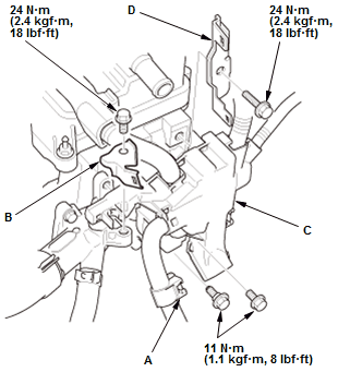
- Remove the harness clamp (A)
- Remove the bracket (B)
- Move the harness holder (C)
- Remove the bracket (D).
12. Cylinder Head Cover - Remove
13. Rocker Arm Assembly - Remove
14. Camshaft Sprocket - Remove
15. Camshaft - Remove
.png)
Fig. 3: Cam Shaft Thrust Cover With Torque Specification
- Remove the camshaft thrust cover (A)
- Pull out the camshaft.
16. All Removed Parts - Install
- Install the parts in the reverse order of removal.
CAMSHAFT SPROCKET REMOVAL AND INSTALLATION
Removal & Installation
1. Cam Chain - Remove
2. Rocker Arm Assembly - Remove
3. Camshaft Sprocket - Remove
.png)
Fig. 4: Camshat Sprocket With Torque Specification
- Hold the camshaft with a 27 mm open-end wrench
- Remove the camshaft sprocket.
4. All Removed Parts - Install
- Install the parts in the reverse order of removal.
NOTE:- Apply new engine oil to the threads of the camshaft sprocket mounting bolt.
- Before installing cylinder head cover, adjust the valve clearance.
- After installing all the removed parts, clear and lean the CKP pattern.
READ NEXT:
 Connecting Rod Bearing Replacement
Replacement
1. Engine/Transmission - Remove
2. Transmission - Remove
Remove the transmission:
M/T
CVT
3. Pressure Plate, Clutch Disc, and Flywheel - Remove (M/T)
4. Drive Plate - Remove (CV
Crankshaft Main Bearing Replacement
Replacement
1. Engine/Transmission - Remove
2. Transmission - Remove
Remove the transmission:
M/T
CVT
3. Pressure Plate, Clutch Disc, and Flywheel - Remove (M/T)
4. Drive Plate - Remove (CV
Crankshaft Pulley Removal and Installation
Special Tools Required
Holder Handle
07JAB-001020B
Pulley Holder
Attachment, 50 x
39 mm 07MABPY30100
Socket, 19 mm
07JAA-001020A
or equivalent
Removal
1. Right Front Wheel - Remove
2. Right Front S
SEE MORE:
Immobilizer Key Registration
Procedure
1. Immobilizer Key - Register
NOTE:
The HDS is required for registration of the immobilizer keys.
Programming the immobilizer also programs the keyless transmitter.
Check for aftermarket electrical equipment that can cause problems with
transponder operation.
The immobilizer-keyless
Navigation System Symptom Troubleshooting - Audio-Navigation Unit
Illumination Does Not Work
NOTE:
Check the vehicle 12 volt battery condition first.
Check for B-CAN DTCs and resolve them before troubleshooting.
Check the connectors for poor connections or loose terminals.
1. Problem verification:
Turn the vehicle to the ON mode.
Turn the combination lighting switch to the parking l
