Honda HR-V: Assembling Piston & Connecting Rod
NOTE: Examples used in this article are general in nature and do not necessarily relate to a specific engine or system. Illustrations and procedures have been chosen to guide mechanic through engine overhaul process. Descriptions of processes of cleaning, inspection, assembly and machine shop practice are included.
Always refer to appropriate engine overhaul article, if available, in the ENGINES section for complete overhaul procedures and specifications for the vehicle being repaired.
Install piston on connecting rod for corresponding cylinder. Ensure reference marking on top of piston corresponds with connecting rod and cap number. See Fig. 14.
Lubricate piston pin and install in connecting rod. Ensure piston pin retainers are fully seated (if equipped). On pressed type piston pins, follow manufacturer's recommended procedure to avoid distortion or breakage.
.png)
Fig. 14: Installing Typical Piston Pin
CHECKING PISTON RING CLEARANCES
NOTE: Examples used in this article are general in nature and do not necessarily relate to a specific engine or system. Illustrations and procedures have been chosen to guide mechanic through engine overhaul process. Descriptions of processes of cleaning, inspection, assembly and machine shop practice are included.
Always refer to appropriate engine overhaul article, if available, in the ENGINES section for complete overhaul procedures and specifications for the vehicle being repaired.
Piston rings must be checked for side clearance and end gap. To check end gap, install piston ring in cylinder in which it is to be installed. Using an inverted piston, push ring to bottom of cylinder in smallest cylinder diameter.
Using feeler gauge, check ring end gap. See Fig. 15. Piston ring end gap must be within specification. Ring breakage will occur if insufficient ring end gap exists.
Some manufacturers permit correcting insufficient ring end gap by using a fine file while other manufacturers recommend using another ring set. Mark rings for proper cylinder installation after checking end gap.
.png)
Fig. 15: Checking Piston Ring End Gap
For checking side clearance, install rings on piston. Using feeler gauge, measure clearance between piston ring and piston ring land. Check side clearance in several areas around piston. Side clearance must be within specification.
If side clearance is excessive, piston ring grooves can be machined to accept oversize piston rings (if available).
Normal practice is to replace piston.
PISTON & CONNECTING ROD INSTALLATION
NOTE: Examples used in this article are general in nature and do not necessarily relate to a specific engine or system. Illustrations and procedures have been chosen to guide mechanic through engine overhaul process. Descriptions of processes of cleaning, inspection, assembly and machine shop practice are included.
Always refer to appropriate engine overhaul article, if available, in the ENGINES section for complete overhaul procedures and specifications for the vehicle being repaired.
Cylinders must be honed prior to piston installation. See CYLINDER HONING under CYLINDER BLOCK.
Install upper connecting rod bearings. Lubricate upper bearings with engine oil. Install lower bearings in rod caps. Ensure bearing tabs are properly seated. Position piston ring gaps according to manufacturer's recommendations. See Fig. 16. Lubricate pistons, rings and cylinder walls.
.png)
Fig. 16: Positioning Typical Piston Ring End Gap
Install ring compressor. Use care not to rotate piston rings. Compress rings with ring compressor. Install plastic tubing protectors over connecting rod bolts. Install piston and connecting rod assembly. Ensure piston notch, arrow or FRONT mark is toward front of engine. See Fig. 17.
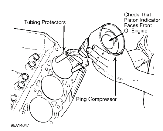
Fig. 17: Installing Piston & Connecting Rod Assembly
Carefully tap piston into cylinder until rod bearing is seated on crankshaft journal. Remove protectors. Install rod cap and bearing. Lightly tighten connecting rod bolts. Repeat procedure for remaining cylinders. Check bearing clearance. See MAIN & CONNECTING ROD BEARING CLEARANCE.
Once clearance is checked, lubricate journals and bearings. Install bearing caps. Ensure marks are aligned on connecting rod and cap. Tighten rod nuts or bolts to specification. Ensure rod moves freely on crankshaft.
Check connecting rod side clearance. See CONNECTING ROD SIDE CLEARANCE.
CONNECTING ROD SIDE CLEARANCE
NOTE: Examples used in this article are general in nature and do not necessarily relate to a specific engine or system. Illustrations and procedures have been chosen to guide mechanic through engine overhaul process. Descriptions of processes of cleaning, inspection, assembly and machine shop practice are included.
Always refer to appropriate engine overhaul article, if available, in the ENGINES section for complete overhaul procedures and specifications for the vehicle being repaired.
Position connecting rod toward one side of crankshaft as far as possible. Using feeler gauge, measure clearance between side of connecting rod and crankshaft. See Fig. 18. Clearance must be within specification.
Check for improper bearing installation, wrong bearing cap or insufficient bearing clearance if side clearance is insufficient. Connecting rod may require machining to obtain proper clearance. Excessive clearance usually indicates excessive wear at crankshaft. Crankshaft must be repaired or replaced.
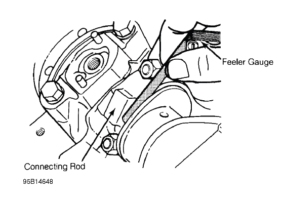
Fig. 18: Measuring Connecting Rod Side Clearance
READ NEXT:
 Main & Connecting Rod Bearing Clearance
NOTE: Examples used in this article are general in nature and do not
necessarily relate
to a specific engine or system. Illustrations and procedures have been chosen
to guide mechanic through engine
Removal, Cleaning & Inspection, Installation
REMOVAL
NOTE: Examples used in this article are general in nature and do not
necessarily relate
to a specific engine or system. Illustrations and procedures have been chosen
to guide mechanic through
SEE MORE:
Manual Transmission
MANUAL TRANSMISSION TROUBLE SHOOTING
NOTE: This is GENERAL information. This article is not intended to be
specific to any
unique situation or individual vehicle configuration. The purpose of this
Trouble
Shooting information is to provide a list of common causes to problem
symptoms. For model-spe
DTC Troubleshooting 111-11: Back-Up Light Switch Stuck OFF
NOTE:
Before you troubleshoot, review the general troubleshooting information.
If DTC 86-11 is indicated at the same time, do the DTC 86-11
troubleshooting first.
1. Back-up lights check:
Turn the vehicle to the ON mode.
Check the back-up lights when the shift lever is in reverse.
Are the
