Honda HR-V: Ignition System - Inspection & Adjustment
INSPECTION & ADJUSTMENT
IGNITION TIMING INSPECTION
Inspection
1. HDS DLC - Connect
NOTE: For specific operations, refer to the user's manual that came with the HDS. Make sure the HDS is loaded with the latest software.
- Turn the vehicle to the OFF (LOCK) mode.
- Connect the HDS to the DLC.
- Turn the vehicle to the ON mode.4. Make sure the HDS communicates with the vehicle. If it does not communicate, go to the DLC circuit troubleshooting.
2. DTC - Check - Refer to: How to Troubleshoot the Fuel and Emissions Systems, or How to Troubleshoot the CVT System(CVT)
NOTE: If a DTC is present, diagnose and repair the cause before continuing with this inspection.
3. Harness Cover - Remove
4. Engine - Warm Up
- Start the engine. Hold the engine speed at 3, 000 rpm with no load (M/T in neutral, CVT in P or N) until the radiator fan comes on, then let it idle.
5. Idle Speed - Check
6. SCS - Short
- Turn the vehicle to the OFF (LOCK) mode
- Jump the SCS line with the HDS.
7. Ignition Timing - Inspect
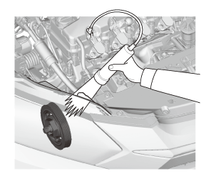
- Start the engine
- Connect the timing light to the No. 1 ignition coil harness.
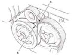
- Aim the light toward the pointer (A) on the drive belt auto-tensioner bracket. Check the ignition timing under a no load condition (headlights, blower fan, rear window defogger, and air conditioner are turned off).
Ignition Timing
USA and Canada models: 1 Â+-2 ºBTDC (RED mark (B) ) at idle (M/T in neutral, CVT in P or N)
Mexico models: 8 Â+-2 ºBTDC (RED mark (B) ) at idle (M/T in neutral, CVT in P or N)
- If the ignition timing differs from the specification, check the camshaft timing. If the camshaft timing is OK, update the PCM if it does not have the latest software, or substitute a known-good PCM, then recheck. If the system works properly, and the PCM was substituted, replace the original PCM.5. Disconnect the HDS and the timing light.
8. All Removed Parts - Install
- Install the parts in the reverse order of removal.
SPARK PLUG INSPECTION
Inspection
1. Ignition Coil and Spark Plug - Remove
2. Spark Plug - Inspect
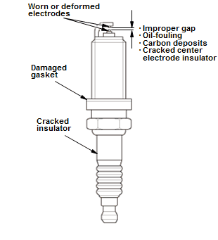
- Inspect the electrodes and the ceramic insulator:
- Burned or worn electrodes may be caused by these
conditions:
- Advanced ignition timing
- Loose spark plug
- Plug heat range too hot
- Insufficient cooling
- Fouled plugs may be caused by these conditions:
- Retarded ignition timing
- Oil in combustion chamber
- Incorrect spark plug gap
- Plug heat range too cold
- Excessive idling/low speed running
- Clogged air cleaner element
- Deteriorated ignition coils
- Burned or worn electrodes may be caused by these
conditions:
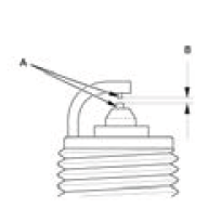
- Replace the plug at the specified interval, or if the center electrode (A) is rounded, or if the spark plug gap (B) is out of specification, or if the spark plug electrode is dirty or contaminated.
NOTE:
- Do not adjust the gap of iridium tip plugs.
- Do not use a plug cleaner.
Electrode Gap
Standard (New): 1.0-1.1 mm (0.039-0.043 in)
3. All Removed Parts - Install
- Install the parts in the reverse order of removal.
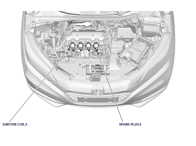
COMPONENT LOCATION INDEX
IGNITION SYSTEM COMPONENT LOCATION INDEX
READ NEXT:
 Cylinder Head Cover Removal and Installation
Removal
1. Harness Cover - Remove
2. Positive Cable and Connector (Alternator) - Disconnect
NOTE: Remove the positive cable clamp at the same time.
3. Cylinder Head Cover Harness Holder - Move
Disc
Cylinder Head Removal and Installation
Removal
NOTE:
Use fender covers to avoid damaging painted surfaces.
To avoid damaging the wiring and terminals, unplug the wiring connectors
carefully while holding the
connector portion.
Conne
SEE MORE:
Secondary Fuel Gauge Sending Unit Test (AWD)
Test
1. Fuse - Check
Check the No. B21 (10 A) +B BACK UP fuse in the under-hood fuse/relay
box and the No. C34
(7.5 A) IG1 METER fuse in the under-dash fuse/relay box before testing.
2. Body Electrical DTCs - Check
Check for body electrical system DTCs.
If no problem is found, go to the ne
General Information
ENGINE CONFIGURATION
Fig. 2: Engine Configuration With Drive Belt Routing And Egine Rotation
CHECK
THROTTLE BODY CARBON ACCUMULATION CHECK
Test
1. HDS - Connect
2. Throttle Body - Test
Start the engine. Hold the engine speed at 3, 000 rpm without load (CVT
in P or N, M/T in neutral)
until the
