Honda HR-V: Cylinder Head Cover Removal and Installation
Removal
1. Harness Cover - Remove
2. Positive Cable and Connector (Alternator) - Disconnect
NOTE: Remove the positive cable clamp at the same time.
3. Cylinder Head Cover Harness Holder - Move
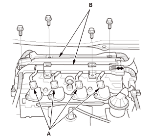
- Disconnect the connectors (A)
- Move the harness holders (B).
4. Breather Hose - Disconnect
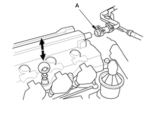
- Remove the dipstick
- Disconnect the breather hose (A).
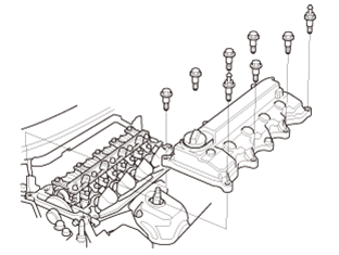
5. Cylinder Head Cover - Remove
Installation
1. Cylinder Head Cover - Install
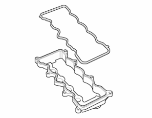
- Thoroughly clean the head cover gasket and the groove of the cylinder head cover.
NOTE: Check and, if necessary, replace the head cover gasket.
- Install the head cover gasket in the groove of the cylinder head cover.
Make sure the head cover gasket is seated securely.
- Apply liquid gasket to the oil pump and the cylinder head mating areas.
- Loosely install the cylinder head cover.
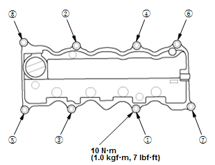
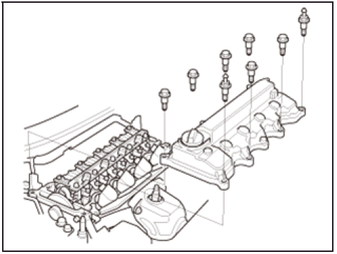
Fig. 1: Cylinder Head Cover Tightening Sequence With Torque Specifications
- Tighten the bolts in three steps; tighten the bolts until the bolts sit on the cylinder head cover, tighten the bolts until the gasket is compressed, tighten the bolts to specified torque.
2. Breather Hose - Connect
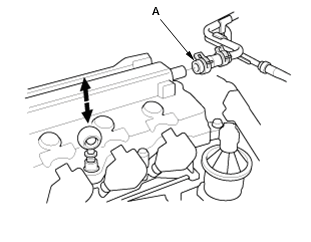
- Install the dipstick
- Connect the breather hose (A).
3. Cylinder Head Cover Harness Holder - Install
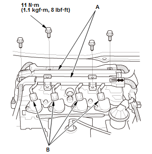
Fig. 2: Cylinder Head Cover Harness Holder With Torque Specifications
- Install the harness holders (A)
- Connect the connectors (B).
4. Positive Cable and Connector (Alternator) - Connect
NOTE: Install the positive cable clamp at the same time.
5. Harness Cover - Install
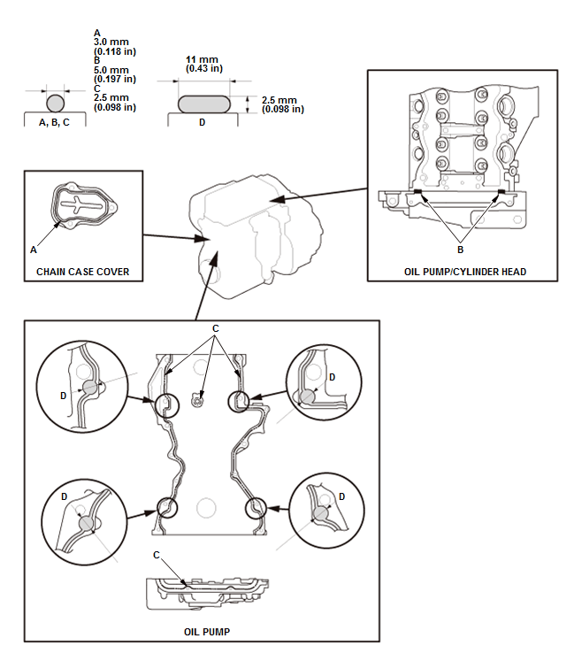
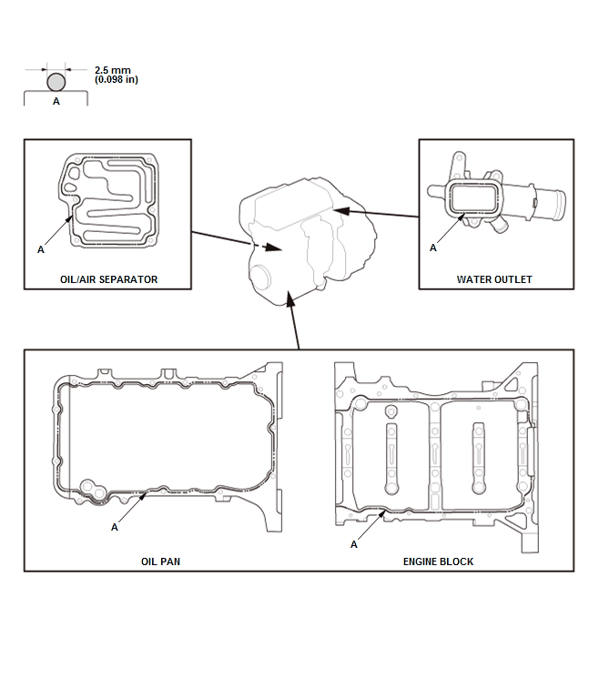
CYLINDER HEAD LIQUID GASKET APPLYING PROCEDURE
Procedure
1. Liquid Gasket - Apply
NOTE:
- Remove all of the old liquid gasket of the mating surfaces of each part and clean.
- Apply liquid gasket (P/N 08717-0004, 08718-0003, or 08718-0009). Install the component within 5 minutes of applying the liquid gasket.
- If too much time has passed after applying the liquid gasket, remove the old liquid gasket and residue, then reapply new liquid gasket.
- Wait at least 30 minutes before filling the engine with oil.
- Do not run the engine for at least 3 hours after installing the parts.
READ NEXT:
 Cylinder Head Removal and Installation
Removal
NOTE:
Use fender covers to avoid damaging painted surfaces.
To avoid damaging the wiring and terminals, unplug the wiring connectors
carefully while holding the
connector portion.
Conne
Cylinder Head Assembly - Inspection & Adjustment
INSPECTION & ADJUSTMENT
CYLINDER HEAD INSPECTION FOR WARPAGE
Inspection
1. Cylinder Head - Remove
2. Cylinder Head Warpage - Inspect
Check the cylinder head for warpage. Measure along
the edg
SEE MORE:
Symptom Troubleshooting
CHARGING SYSTEM SYMPTOM TROUBLESHOOTING INDEX
CHARGING SYSTEM INDICATOR STAYS ON
Diagnostic procedure
1. Gauges Self-Diagnostic Function
CIRCUIT DIAGRAM
CHARGING SYSTEM CIRCUIT DIAGRAM
Without Keyless Access System
With Keyless Access System
WIRING DIAGRAM
CHARGING SYSTEM ELECTRONIC WIRING DIAGRA
Functional Setup - Audio System Diagnostic Mode
Select the item you want to check.
Backup Data Clear
Save Users Memory
LaneWatch (With Lanewatch)
Phone Picture
Anti-Theft Skip
Other
Backup Data Clear
This screen initializes the back-up data in the audio unit.
All Clear
Cookie Clear (Not available in this model (grayed out) )
Cache Cl
