Honda HR-V: Cylinder Head Removal and Installation
Removal
NOTE:
- Use fender covers to avoid damaging painted surfaces.
- To avoid damaging the wiring and terminals, unplug the wiring connectors carefully while holding the connector portion.
- Connect the HDS to the DLC, and monitor ECT SENSOR 1. To avoid damaging the cylinder head, wait until the engine coolant temperature drops below 100 ºF (38 ºC) before loosening the cylinder head bolts.
- Mark all wiring and hoses to avoid misconnection. Also, be sure that they do not contact other wiring or hoses, or interfere with other parts.
1. Fuel Pressure - Relieve
NOTE: After relieving the fuel pressure, do not connect the quick-connect fitting.
2. Engine Coolant - Drain
3. Intake Manifold - Remove
4. Fuel Injector and Rail Assembly - Remove
5. Rocker Arm Oil Control Valve - Remove
6. Ignition Coil and Spark Plug - Remove
7. Connector (CMP Sensor) - Disconnect
8. Connector (ECT Sensor 1) - Disconnect - Refer to: ECT Sensor 1 Removal and Installation, or ECT Sensor 2 Removal and Installation
9. Connector (EGR Valve) - Disconnect
10. Positive Cable and Connector (Alternator) - Disconnect
NOTE: Remove the positive cable clamp at the same time.
11. Cylinder Head Cover Harness Holder - Move
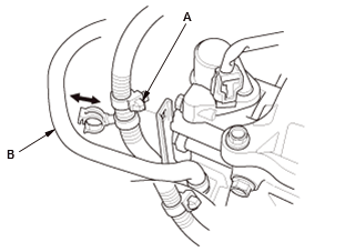
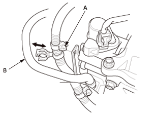
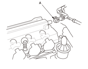
12. Breather Hose - Disconnect

- Disconnect the breather hose (A).
13. Harness Holder - Move
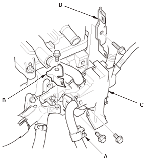
- Remove the harness clamp (A)
- Remove the bracket (B)
- Move the harness holder (C)
- Remove the bracket (D).
14. Harness Clamp and PCV Hose Clamp - Remove
- Remove the harness clamp (A) and the PCV hose clamp (B).
15. Water Outlet - Remove
16. Heater Outlet - Remove
17. Thermostat Housing - Remove
18. Exhaust Pipe A - Remove
19. Warm Up TWC - Remove (USA and Canada models) - Refer to: Warm Up TWC Removal and Installation (KA/KC), or Under-Floor TWC Removal and Installation (KA/KC)
20. Catalytic Converter - Remove (Mexico models) - Refer to: Warm Up TWC Removal and Installation (KA/KC), or Under-Floor TWC Removal and Installation (KA/KC)
21. Cylinder Head Cover - Remove
22. Cam Chain - Remove
23. Cylinder Head - Remove
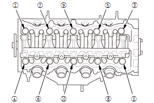
Fig. 3: Cylinder Head Bolts Loostening Sequence
- Remove the cylinder head bolts. To prevent warpage, loosen the bolts in sequence, 1/3 turn at a time; repeat the sequence until all bolts are loosened
- Remove the cylinder head
24. Heat Insulator - Remove
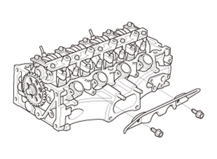
- Remove the heat insulator as needed
Installation
1. Heat Insulator - Install
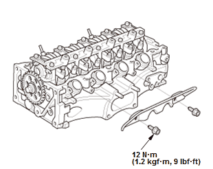
Fig. 4: Heat Insulator With Torque Specifications
- If the heat insulator is removed, install the heat insulator.
2. No. 1 Piston at Top Dead Center - Set
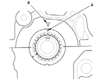
- Set the crankshaft to top dead center (TDC). Align the TDC mark (A) on the crankshaft sprocket with the pointer (B) on the engine block.
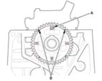
- Set the camshaft to TDC. The "UP" mark (A) on the camshaft sprocket should be at the top, and the TDC grooves (B) on the camshaft sprocket should aline up with the top edge of the cylinder head.
3. Cylinder Head - Install
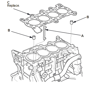
- Clean the cylinder head and the engine block surfaces
- Install a new coolant separator (A) in the engine block whenever the engine block is replaced
- Install the dowel pins (B) and a new cylinder head gasket (C)
- Install the cylinder head on the engine block.
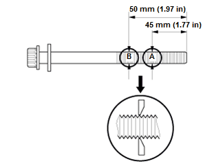
- Measure the diameter of each cylinder head bolt at point A and point B
- If either diameter is less than 10.6 mm (0.417 in), replace the cylinder head bolt
- Apply new engine oil to the threads and flange of all cylinder head bolts.
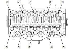
Fig. 5: Cylinder Head Bolts Tightening Sequence
- Torque the cylinder head bolts in sequence to 40 N.m (4.1 kgf.m, 30 lbf.ft), using a beam-type torque wrench. When using a preset click-type torque wrench, be sure to tighten slowly and do not overtighten. If a bolt makes any noise while you are torquing it, loosen the bolt and retighten it from the first step.
.png)
- After torquing, tighten all cylinder head bolts in two steps (90 º per step using the sequence shown in step 8). If you are using a new cylinder head bolt, tighten the bolt an extra 60 º.
NOTE: Remove the cylinder head bolt if you tightened it beyond the specified angle, and go back to step 5 of the procedure. Do not loosen it back to the specified angle.
4. Cam Chain - Install
5. Valve Clearance - Adjust
6. Cylinder Head Cover - Install
NOTE: Do not Install the cylinder head harness holder in this step.
7. Warm Up TWC - Install (USA and Canada models) - Refer to: Warm Up TWC Removal and Installation (KA/KC), or Under-Floor TWC Removal and Installation (KA/KC)
8. Catalytic Converter - Install (Mexico models) - Refer to: Warm Up TWC Removal and Installation (KA/KC), or Under-Floor TWC Removal and Installation (KA/KC)
9. Exhaust Pipe A - Install
10. Thermostat Housing - Install
11. Heater Outlet - Install
12. Water Outlet - Install
13. Harness Clamp and PCV Hose Clamp - Install
- Install the harness clamps (A) and the PCV hose clamp (B).
14. Harness Holder - Install
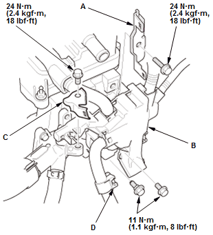
Fig. 6: Harness Holder With Torque Specifications
- Install the bracket (A) and the harness holder (B)
- Install the bracket (C) and the harness clamp (D).
15. Breather Hose - Connect
- Connect the breather hose (A).
16. Cylinder Head Cover Harness Holder - Install
17. Positive Cable and Connector (Alternator) - Connect
NOTE: Install the positive cable clamp at the same time.
18. Connector (EGR Valve) - Connect
19. Connector (ECT Sensor 1) - Connect - Refer to: ECT Sensor 1 Removal and Installation, or ECT Sensor 2 Removal and Installation
20. Connector (CMP Sensor) - Connect
21. Spark Plug and Ignition Coil - Install
22. Rocker Arm Oil Control Valve - Install
23. Fuel Injector and Rail Assembly - Install
24. Intake Manifold - Install
25. Fuel Feed Hose (Fuel Rail Side) - Connect
26. Drive Belt Auto-Tensioner - Install
27. Fuel Leak - Inspect
- Turn the vehicle to the ON mode, but do not operate the starter. After the fuel pump runs for about 2 seconds, the fuel rail will be pressurized. Repeat this two or three times, then check for fuel leakage.
28. Engine Coolant - Refill/Air Bleed
29. Ignition Timing - Inspect
30. CKP Pattern - Clear/Learn
READ NEXT:
 Cylinder Head Assembly - Inspection & Adjustment
INSPECTION & ADJUSTMENT
CYLINDER HEAD INSPECTION FOR WARPAGE
Inspection
1. Cylinder Head - Remove
2. Cylinder Head Warpage - Inspect
Check the cylinder head for warpage. Measure along
the edg
A/F Sensor Removal and Installation
Special Tools Required
O2 Sensor
Wrench Snap-on
S6176 or
equivalent,
commercially
available
Removal & Installation
1. A/F Sensor - Remove
Fig. 1: A/F Sensor With Torque Specification
Disconnec
SEE MORE:
Oil Check
We recommend that you check the engine oil level every time you refuel.
Park the vehicle on level ground.
Wait approximately three minutes after turning the engine off before you check
the
oil.
1. Remove the dipstick (orange).
2. Wipe the dipstick with a clean cloth or
paper towel.
3. Insert th
Audio Check - Audio System Diagnostic Mode
These screens allow you to troubleshoot the audio function.
ANC Check (Not supported)
Speaker Check (B)
Speaker Check
NOTE:
Make sure the audio system is off before this diagnosis.
While doing the diagnosis, the fader and the balance positions are set
to the center.
This diagnosis checks
