Honda HR-V: Indicators
.png)
*1:Models with the smart entry system have an ENGINE START/STOP button instead of an ignition switch.
.png)
*1:Models with the smart entry system have an ENGINE START/STOP button instead of an ignition switch.
.png)
*1:Models with the smart entry system have an ENGINE START/STOP button instead of an ignition switch.
.png)
*1:Models with the smart entry system have an ENGINE START/STOP button instead of an ignition switch.
.png)
*1:Models with the smart entry system have an ENGINE START/STOP button instead of an ignition switch.
.png)
*1:Models with the smart entry system have an ENGINE START/STOP button instead of an ignition switch.
.png)
*1:Models with the smart entry system have an ENGINE START/STOP button instead of an ignition switch.
.png)
*1:Models with the smart entry system have an ENGINE START/STOP button instead of an ignition switch.
.png)
.png)
*1:Models with the smart entry system have an ENGINE START/STOP button instead of an ignition switch.
.png)
*1:Models with the smart entry system have an ENGINE START/STOP button instead of an ignition switch.
.png)
*1:Models with the smart entry system have an ENGINE START/STOP button instead of an ignition switch.
.png)
*1:Models with the smart entry system have an ENGINE START/STOP button instead of an ignition switch.
* Not available on all models
Information Display Warning and Information Messages
The following messages appear only on the information display.
.png)
Models with smart entry system
.png)
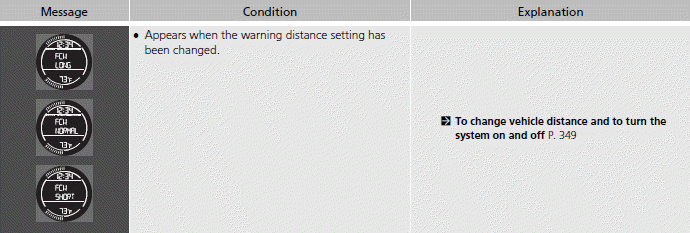
Models with FCW
READ NEXT:
 Gauges and Displays
Gauges
Gauges include the speedometer, tachometer and related indicators. They are
displayed when the ignition switch is in ON (II)*1.
■Speedometer
Displays your driving speed in mph and km/h.
■Ta
Clock
Adjusting the Clock
Models without navigation system
You can adjust the time in the clock display with the ignition switch is in
ON (II)*1.
■Adjusting the Time
■ Display audio system
1. Select th
SEE MORE:
Maintenance Minder General Information (KA/KC Models)
Maintenance Minder
The Maintenance Minder is an important feature of the information display.
Based on engine and transmission operating conditions, and accumulated engine
revolutions, the HR-V's onboard
computer (PCM) calculates the remaining engine oil and the transmission fluid
life. The syste
Shifting (Manual transmission models)
■Shift Lever Operation
Fully depress the clutch pedal to operate the shift lever and change gears,
then
slowly release the pedal.
Depress the clutch pedal, and pause for a few seconds before shifting into (R),
or
shift into one of the forward gears for a moment. This stops the gears so they
do
