Honda HR-V: Lift and Support Points
NOTE: If you are going to remove heavy components such as suspension or the fuel tank from the rear of the vehicle, first support the front of the vehicle with tall safety stands. When substantial weight is removed from the rear of the vehicle, the center of gravity can change, causing the vehicle to tip forward on the lift.
Vehicle Lift
1. Position the lift pads (A) under the vehicle's front support points (B) and rear support points (C).

Be sure the lift pads are properly placed to avoid damaging the vehicle.
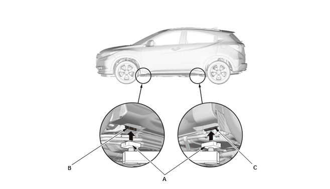
2. Raise the lift a few inches, and rock the vehicle gently to be sure it is firmly supported.
3. Raise the lift to its full height, and inspect the vehicle support points for solid contact with the lift pads.
Safety Stands
To support the vehicle on safety stands, use the same support points as for a vehicle lift. Always use safety stands when working on or under any vehicle that is supported only by a jack.
Floor Jack
1. When lifting the front of the vehicle, set the parking brake. When lifting the rear of the vehicle, put the shift lever in reverse (M/T model) or P (CVT model).
2. Block the wheels that are not being lifted.
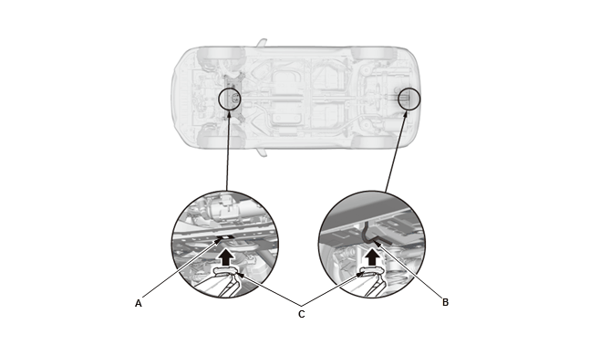
3. Position the floor jack under the front jacking bracket (A) or the rear jacking bracket (B).
Center the jacking bracket on the jack lift platform (C), and jack up the vehicle high enough to fit the safety stands under it.
Be sure the floor jack is properly placed to avoid damaging the vehicle.
4. Position the safety stands under the support points, and adjusts them so the vehicle is level side-to-side.
5. Lower the vehicle onto the stands.
READ NEXT:
 Parts Marking (KA/KC Models)
To deter vehicle theft, certain major components are marked with the vehicle
identification number (VIN). Original parts have self-adhesive labels.
Replacement body parts have generic self-adhesive
A Few Words About Safety
Service Information
The service and repair information contained in this manual is intended for
use by qualified, professional technicians. Attempting service or repairs
without the proper training,
Lubricants and Fluids (KA/KC Models)
For the details of the lubrication points and the type of lubricants to be
applied, refer to the illustrated index and the various work procedures (such as
Assembly/Reassembly, Replacement,
Overha
SEE MORE:
Connector Inputs and Outputs
AUDIO SYSTEM ELECTRONIC WIRING DIAGRAM
Please see appropriate system wiring diagram. ELECTRICAL SYSTEM - TESTING &
TROUBLESHOOTING
AUDIO UNIT CONNECTOR FOR INPUTS AND OUTPUTS (COLOR AUDIO TYPE (5-INCH
SCREEN) )
Connector Index
Audio Unit Connector A (24P)
Audio Unit Connector C (24P)
Audio Uni
Rear Window Defogger System Description - Control/Function
The Timer Function (Without Climate Control)
The rear window defogger provides the timer control function that is
controlled by the HVAC control unit. The
timer control is operated by turning the vehicle to the ON mode, then turn on
the rear window defogger switch.
The timer operating time varies
