Honda HR-V: Overhaul
STARTER OVERHAUL
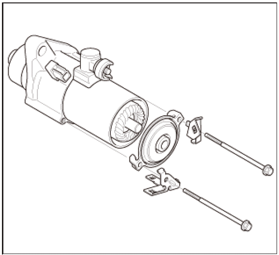
Exploded View
NOTE: Do not wipe off the special grease applied to the area of the starter marked with an asterisk (*) when you disassemble or assemble it.
1. Starter - Exploded View
Exploded View
.png)
Fig. 1: Starter Exploded View With Torque Specifications
Disassembly
NOTE: Refer to the Exploded View if needed during this procedure.
1. End Cover - Remove
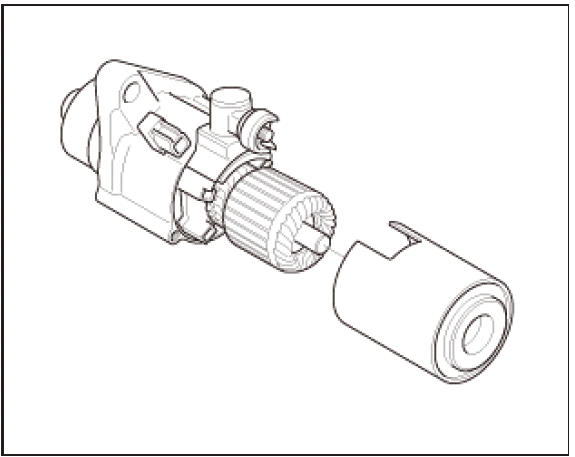
2. Armature Housing - Remove
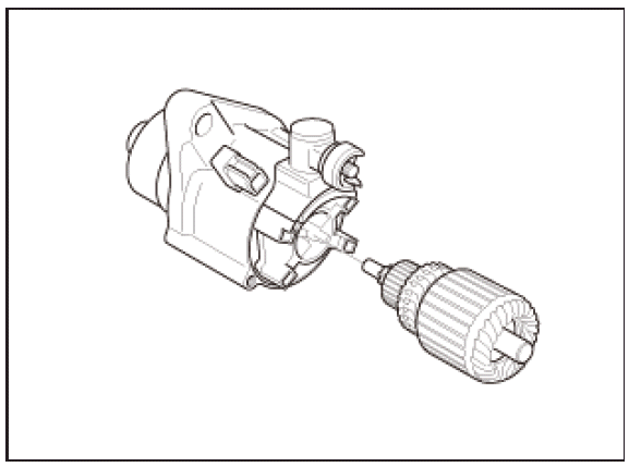
3. Armature - Remove
4. Armature - Inspect
.png)
- Inspect the armature for wear or damage from contact with the permanent magnet. If there is wear or damage, replace the armature.
.png)
- Check the commutator (A) surface. If the surface is dirty or burnt, resurface it with an emery cloth or a lathe to the specifications in step 3, or recondition with #500 or #600 sandpaper (B).
.png)
- Check the commutator diameter with a digital caliper or dial type caliper. If the diameter is below the service limit, replace the armature.
Standard (New): 28.0-28.1 mm (1.102-1.106 in)
Service Limit: 27.5 mm (1.083 in)
.png)
- Measure the commutator (A) runout:
- If the commutator runout is within the service limit, check the commutator for carbon dust or brass chips between the segments.
- If the commutator runout is not within the service limit, replace the armature.
Standard (New): 0.02 mm (0.0008 in) max.
Service Limit: 0.05 mm (0.0020 in)
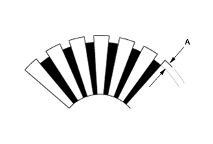
- Use a digital caliper or dial type caliper to check the mica depth (A). If the mica depth is below the service limit, replace the armature.
Standard (New): 0.40-0.50 mm (0.0157-0.0197 in)
Service Limit: 0.15 mm (0.0059 in)
- Use an ohmmeter to check for continuity between the segments of the commutator. If there is an open circuit between any of the segments, replace the armature.
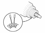
- Place the armature (A) on an armature tester (B). Hold a hacksaw blade (C) on the armature core. If the blade is attracted to the core while the core is turned, the armature is shorted. Replace the armature.
- Use an ohmmeter to check for continuity between the commutator (A) and the armature coil core (B), and between the commutator and the armature shaft (C). If there is continuity, replace the armature.
5. Brush Holder Assembly - Remove
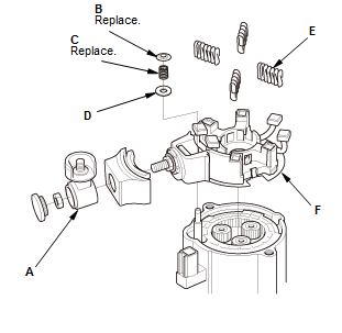
- Remove the terminal insulator (A)
- Remove the push nut (B), the contact spring (C), the moving contact (D), and the brush springs (E)
- Remove the brush holder assembly (F).
6. Brush Holder - Test
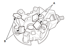
- Check for continuity between the (+) brushes (A) and the (-) brushes (B). If there is continuity, replace the brush holder assembly.
7. Brush - Inspect
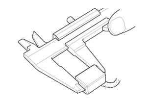
- Measure the brush length. If it is shorter than the service limit, replace the brush holder assembly.
Standard (New): 11.1-11.5 mm (0.437-0.453 in)
Service Limit: 4.3 mm (0.169 in)
8. Planetary Gear - Inspect
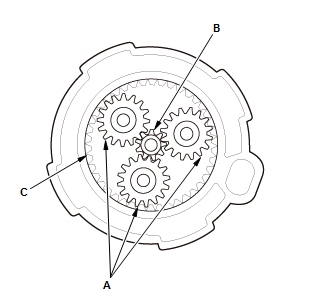
- Check the planetary gears (A), the gear shaft (B), and the internal ring gear (C). Replace them if they are worn or damaged.
9. Internal Gear - Remove
.png)
10.Switch Plunger, Switch Shaft, and Gear Plunger - Remove
.png)
11.Overrunning Clutch - Inspect
.png)
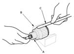
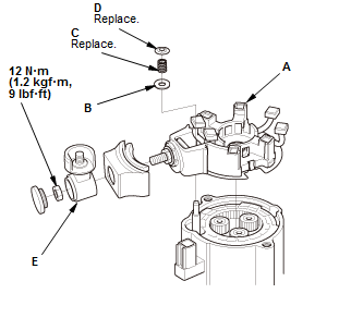
- Hold the drive gear (A), turn the gear shaft (B) counterclockwise. Check that the drive gear comes out to the other end. If the drive gear does not move smoothly, replace the gear cover set
- Hold the drive gear, turn the gear shaft clockwise. The gear shaft should turn freely. If the gear shaft does not turn freely, replace the gear cover set
- If the drive gear is worn or damaged, replace the overrunning clutch assembly; the gear is not available separately.
Reassembly
NOTE: Refer to the Exploded View if needed during this procedure.
1. Switch Plunger, Switch Shaft, and Gear Plunger - Install
.png)
NOTE: Always use a new switch shaft.
2. Internal Gear - Install
.png)
3. Brush Holder Assembly - Install
- Install the brush holder assembly (A)
- Install the moving contact (B), the contact spring (C), and the push nut
(D).
NOTE : Always use a new contact spring and push nut - Install the terminal insulator (E).
4. Armature - Install
.png)
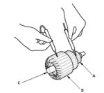
- Install the armature (A) in the brush holder (B)
- Install the brushes into the brush holder.
NOTE : To seat the new brushes, slip a strip of #500 or #600 sandpaper, with the grit side up, between the commutator and each brush, and smoothly rotate the armature. The contact surface of the brushes will be sanded to the same contour as the commutator - While squeezing a brush spring (C), insert it in the hole on the brush holder, and push it until it bottoms. Repeat this for the other three springs.
5. Armature Housing - Install
.png)
6. End Cover - Install
.png)
READ NEXT:
 EGR Function Testing
TEST 1
1980-87 (PORTED EGR VALVE)
Check vacuum hoses for correct routing. Disconnect vacuum hose from EGR
valve. Run engine to operating
temperature. Apply 6 in. Hg to EGR valve. Ensure engine runs r
Ignition System - Service Information
REMOVAL & INSTALLATION
IGNITION COIL AND SPARK PLUG REMOVAL AND INSTALLATION
Removal and Installation
1. Harness Cover - Remove
2. Ignition Coil - Remove
Fig. 1: Ignition Coil With Torque Specif
Ignition System - Inspection & Adjustment
INSPECTION & ADJUSTMENT
IGNITION TIMING INSPECTION
Inspection
1. HDS DLC - Connect
NOTE: For specific operations, refer to the user's manual that came with the
HDS. Make sure the
HDS is loaded wi
SEE MORE:
DTC Troubleshooting C0062-76: Longitudinal Acceleration Sensor (Inside of
Electric Parking Brake Control Unit) Adjustment Condition Incorrect
NOTE:
Before you troubleshoot, review the how to troubleshoot the electric
parking brake system.
Before troubleshooting, check the electric parking brake control unit
for proper mounting. If not properly
installed the electric parking brake control unit may set this code.
1. Problem verifi
Circuit Diagram
EXTERIOR LIGHTS CIRCUIT DIAGRAM
Headlights/Parking Lights/Side Marker Lights/Taillights/License Plate
Lights
Back-Up Lights
Brake Lights
Fog Lights
TURN SIGNAL/HAZARD WARNING LIGHTS CIRCUIT DIAGRAM
LIGHTING CONTROL SENSOR
AUTOMATIC LIGHTING CONTROL UNIT-SENSOR CONNECTOR FOR INPUTS AND OUTPU
