Honda HR-V: Parasitic Load Explanation & Test Procedures
* PLEASE READ THIS FIRST *
NOTE: This is GENERAL information. This article is not intended to be specific to any unique situation or individual vehicle configuration. For model-specific information see appropriate articles where available.
GENERAL INFORMATION
NOTE: This is GENERAL information. This article is not intended to be specific to any unique situation or individual vehicle configuration. For model-specific information see appropriate articles where available.
The term Parasitic Load refers to electrical devices that continue to use or draw current after the ignition switch is turned to OFF position. This small amount of continuous battery draw is expressed in milliamps (mA). On Chrysler vehicles, a typical Parasitic Load should be no more than 30 milliamps (0.030 amps). On Ford Motor Co. and General Motors vehicles produced after 1980, a typical Parasitic Load should be no more than 50 milliamps (0.050 amps).
Vehicles produced since 1980 have memory devices that draw current with ignition off for as long as 20 minutes before shutting down the Parasitic Drain. When Parasitic Load exceeds normal specifications, the vehicle may exhibit dead battery and no-start condition.
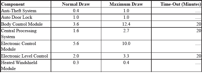
Follow test procedure for checking Parasitic Loads to completion. A brief overview of a suggested test procedure is included along with some typical Parasitic Load specifications. Refer to GENERAL MOTORS PARASITIC LOAD TABLE chart.
TESTING FOR PARASITIC LOAD
NOTE: This is GENERAL information. This article is not intended to be specific to any unique situation or individual vehicle configuration. For model-specific information see appropriate articles where available.
CAUTION: Always turn ignition off when connecting or disconnecting battery cables, battery chargers or jumper cables. DO NOT turn test switch to OFF position (which causes current to run through ammeter or vehicle electrical system).
NOTE: Memory functions of various accessories must be reset after the battery is reconnected.
The battery circuit must be opened to connect test switch (shunt) and ammeter into the circuit. When a battery cable is removed, timer circuits within the vehicle computer are interrupted and immediately begin to discharge.
If in doubt about the condition of the ammeter fuse, test it with an ohmmeter prior to beginning test. An open fuse will show the same reading (00.00) as no parasitic drain. Begin test sequence with the meter installed and on the 10-amp scale. Select lower scale to read parasitic draw.
CHRYSLER IGNITION OFF DRAW (IOD) TEST
To test for excessive IOD, verify that all electrical accessories are OFF. Turn off all lights, remove ignition key, and close all doors and decklid. If the vehicle is equipped with electronic accessories (illuminated entry, automatic load leveler, body computer, or high line radio), allow the system to automatically shut off (time out), up to 3 minutes.
1. Raise the hood and disconnect both battery cables, negative first.
CAUTION: IOD greater than 3 amps may damage millampmeter.
2. Reconnect the negative cable and connect a typical 12-volt test light (low wattage bulb) between the positive cable clamp and the positive battery post. Remove the engine compartment lamp bulb. If the test light does not light, proceed to step 3. If the test light does light, proceed to step, 4. The test light will indicate IOD greater than 3 amps. After higher amperage IOD has been corrected, proceed to step 3.
3. With 12-volt test light still connected (not lit), connect an ammeter (milliampere scale) between the positive cable clamp and the positive battery post, disconnect test light, refer to instructions provided with ammeter being used. A reading of 30 milliamperes or less indicates normal electrical draw. If ammeter reads more than 30 milliamperes, excessive IOD must be corrected.
4. Locate the fuse panel and remove fuses or circuit breakers one at a time, and observe ammeter after each fuse or circuit breaker is removed. If test light goes out and the reading drops below 30 milliamperes when a certain fuse or circuit breaker is removed, that circuit may have a defect.
5. If IOD is detected after all fuses and circuit breakers have been removed, disconnect the 60-way connector at the Single Module Engine Control (SMEC), located outboard of the battery.
6. If excessive IOD is detected after all fused circuits and SMEC have been verified, disconnect the B+ terminal from the alternator. If reading drops below 30 milliamperes, reinstall all fuses and circuit breakers, reconnect B+ terminal at alternator, reconnect battery, and perform alternator diagnostics.
7. Install engine compartment lamp bulb.
TEST PROCEDURE USING TEST SWITCH
1. Turn ignition off. Remove negative battery terminal cable. Install Disconnect Tool (J-38758) test switch male end to negative battery cable. Turn test switch knob to OFF position (current through meter). Install negative battery cable to the female end of test switch.
2. Turn test switch knob to ON position (current through switch). Road test vehicle with vehicle accessories on (radio, air conditioner, etc). After road test, turn ignition switch to LOCKED position and remove key.
Connect ammeter terminals to test switch terminals. See Fig. 1. Select 10-amp scale.
3. Turn off all electrical accessories. Turn off interior lights, underhood lamp, trunk light, illuminated entry, etc. To avoid damaging ammeter or obtaining a false meter reading, all accessories must be off before turning test switch knob to OFF position.
4. Turn test switch knob to OFF position to allow current to flow through ammeter. If meter reads wrong polarity, turn test switch to ON position and reverse leads. Turn test switch to OFF position. Observe current reading. If reading is less than 2 amps, turn test switch to ON position to keep electrical circuits powered-up.
5. Select low amp scale. Switch lead to the correct meter position. Turn test switch to OFF position and compare results to normal current draw. See GENERAL MOTORS PARASITIC LOAD TABLE (MILLIAMPS). If current draw is unusually high for the vehicle's overall electrical system, remove system fuses one at a time until current draw returns to normal.
6. Turn test switch to ON position each time door is opened or fuse is removed. Turn switch to OFF position to read current draw value through meter. When the cause of excessive current drain has been located and repaired, remove test switch and reconnect negative battery cable to the negative battery terminal.
INTERMITTENT PARASITIC LOAD PROBLEMS
Intermittent parasitic load can occur because of a memory device that does not power down with ignition off.
With an intermittent parasitic load, battery draw can be greater than 1.0 amp.
To find an intermittent problem requires that an ammeter and Disconnect Tool (J-38758) test switch be connected and left in the circuit. See Fig. 1. Road test vehicle. After road test, turn ignition off and remove key.
Monitor the milliamps scale for 15-20 minutes after ignition is turned off. This allows monitoring memory devices to determine if they time out and stop drawing memory current. The test switch is needed to protect ammeter when the vehicle is started.
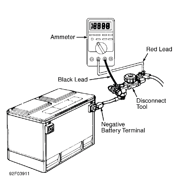
Fig. 1: Connecting Kent-Moore Disconnect Tool (J-38758)
GENERAL MOTORS PARASITIC LOAD
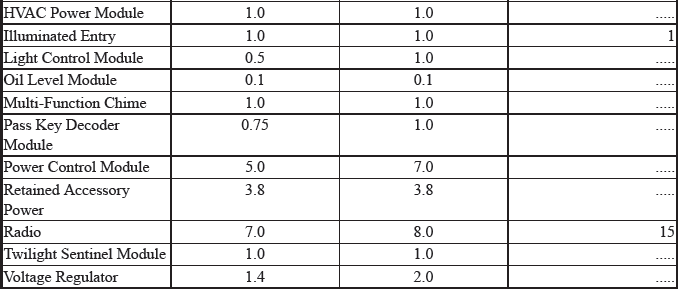
DIODE CHECK & SOLENOID TEST
Fig. 2: Diode Check & Solenoid Test
QUAD DRIVER TEST
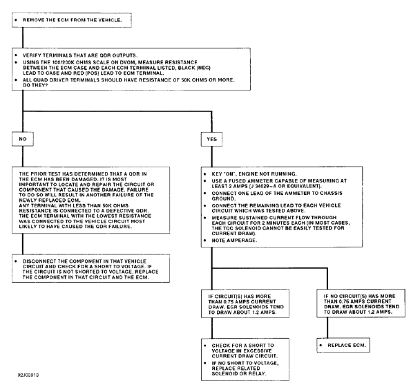
Fig. 3: Quad Driver Test
READ NEXT:
 State Emission Standards
ARIZONA
NOTE: Because of frequent revisions in state emission standards, the
emission
standards listed in this article should only be used as a guide.
ARIZONA EMISSION STANDARDS - PHOENIX & TUCSO
Symptom Check List Worksheets
* PLEASE READ THIS FIRST *
NOTE: This article is intended for general information purposes only. It
does not apply specifically to one make or model.
PURPOSE
NOTE: This article is intended for genera
SEE MORE:
Description
TPMS SYSTEM DESCRIPTION - CALIBRATION
A calibration process is required for the TPMS module to learn the peak tire
resonance values. The calibration procedure must be performed any time the tire
pressures are adjusted,
or when the tires are rotated or replaced. The TPMS calibration procedure is
i
Input Shaft Thrust Clearance Adjustment (CVT)
Special Tools Required
Mainshaft Holder 07GAJ-PG20110
Adjustment
NOTE: If the transmission housing, the torque converter housing, the input
shaft assembly, the stator shaft, or the thrust needle bearing were replaced,
the input shaft thrust clearance must be
adjusted.
1. Input Shaft Thrust Cleara
