Honda HR-V: Traction Control, 4WD, & AWD
TRACTION CONTROL DISABLE
WARNING: Placing a non-compatible vehicle on a single-axle dynamometer could result in a safety hazard to technicians and damage to vehicle. Vehicles which use All- Wheel Drive (AWD) or traction control may not be clearly marked. Use common sense and take all necessary precautions when placing any vehicle on the dynamometer. Determine between full-time 4WD and All-Wheel Drive (AWD) for testing purposes. The following tables include information related to full-time 4WD and AWD vehicles, and how to disable the traction control system (if disengageable).
WARNING: DO NOT operate vehicle on a 2-wheel dynamometer if the DO NOT TEST column is marked.
HONDA
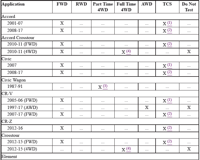
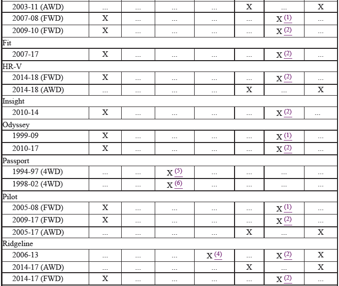
(1) Press TCS (or VSA) switch near left side vent. TCS indicator light will
illuminate when system is
disabled.
(2) Press VSA switch to the left of the steering wheel until a beep is heard.
VSA indicator light will
illuminate when system is disabled.
(3) On A/T models, locate disengagement plate on rear of transaxle case behind
the right front wheel.
Loosen lock bolt on plate. Turn middle bolt on plate. Turn middle bolt
counterclockwise until plate
rotates about 150 degrees and is stopped by lock bolt. Tighten lock bolt. On M/T
models, locate
Orange disengagement lever at rear of engine. Loosen lock bolt at slotted lever.
Turn middle bolt on
lever counterclockwise and tighten lock bolt.
(4) Cannot be shifted to 2WD.
(5) Shift transfer case lever into 2WD position. Ensure 4WD indicator light is
off.
(6) Shift transfer case lever into HIGH position. The 4WD button is located on
left side of dash. Ensure
4WD indicator light is off.
READ NEXT:
 Accessories & Electrical
CHARGING SYSTEM TROUBLE SHOOTING
NOTE: This is GENERAL information. This article is not intended to be
specific to any
unique situation or individual vehicle configuration. The purpose of this
Troub
Air Conditioning & Heat
AIR CONDITIONING TROUBLE SHOOTING
WARNING: This is GENERAL information. This article is not intended to be
specific to any
unique situation or individual vehicle configuration. The purpose of this
T
SEE MORE:
Description
SEAT HEATERS SYSTEM DESCRIPTION - CONTROL/FUNCTION
Heater Control
The front seat heater control switch sets the heater to HI/LO or OFF based on
the front seat heater switch
signals received. The front seat heater control switch receives the front seat
heater switch signals from the
B-CAN via the c
SRS System Description - SRS Unit (KA/KC)
System Diagram
Power supply circuit: Provided to maintain power when battery voltage is
low or in case of power supply damage due to a collision.
Front impact G sensor and side impact G sensor: Detects impact to the
SRS unit as acceleration, and converts it to electrical signal.
Microprocess
