Honda HR-V: Accessories & Electrical
CHARGING SYSTEM TROUBLE SHOOTING
NOTE: This is GENERAL information. This article is not intended to be specific to any unique situation or individual vehicle configuration. The purpose of this Trouble Shooting information is to provide a list of common causes to problem symptoms. For model-specific Trouble Shooting, refer to SUBJECT, DIAGNOSTIC, or TESTING articles available in the section(s) you are accessing.
NOTE: This is GENERAL information. This article is not intended to be specific to any unique situation or individual vehicle configuration. The purpose of this Trouble Shooting information is to provide a list of common causes to problem symptoms. For model-specific Trouble Shooting, refer to SUBJECT, DIAGNOSTIC, or TESTING articles available in the section(s) you are accessing.
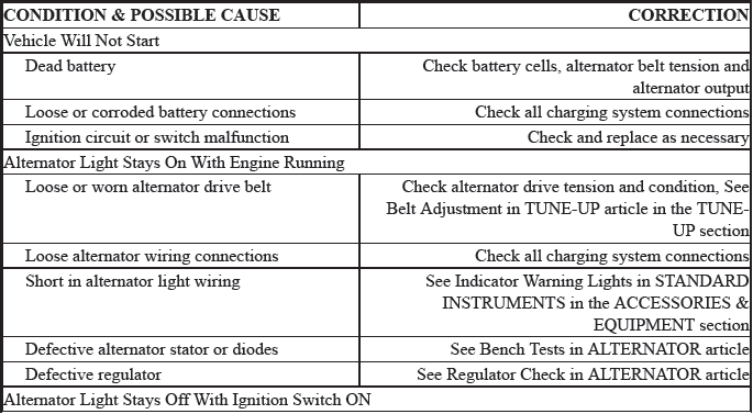
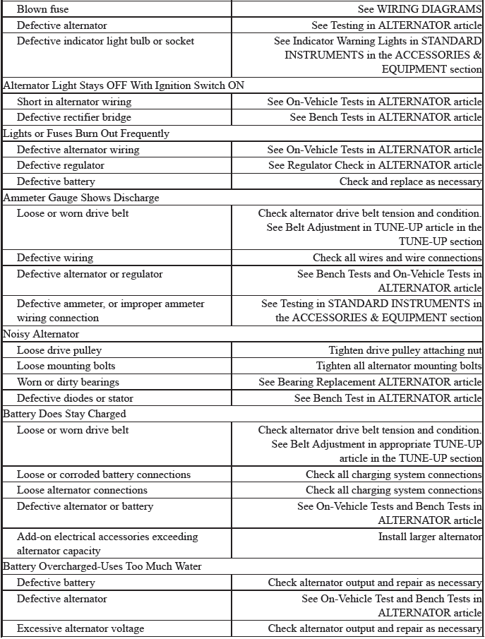
BASIC CHARGING SYSTEM TROUBLE SHOOTING CHART
IGNITION SYSTEM TROUBLE SHOOTING
NOTE: This is GENERAL information. This article is not intended to be specific to any unique situation or individual vehicle configuration. The purpose of this Trouble Shooting information is to provide a list of common causes to problem symptoms. For model-specific Trouble Shooting, refer to SUBJECT, DIAGNOSTIC, or TESTING articles available in the section(s) you are accessing.
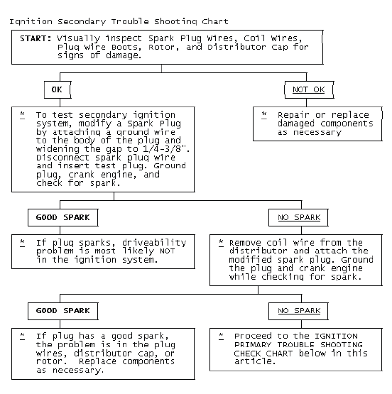
Fig. 1: Ignition Secondary Trouble Shooting Chart
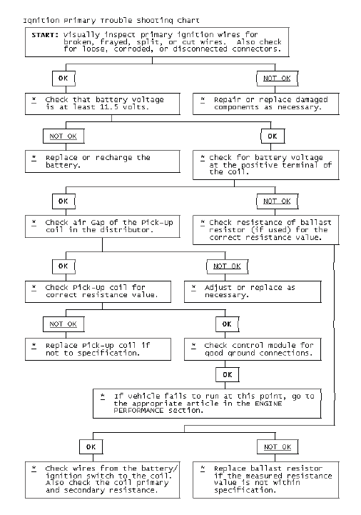
Fig. 2: Ignition Primary Trouble Shooting Chart
STARTER TROUBLE SHOOTING
NOTE: This is GENERAL information. This article is not intended to be specific to any unique situation or individual vehicle configuration. The purpose of this Trouble Shooting information is to provide a list of common causes to problem symptoms. For model-specific Trouble Shooting, refer to SUBJECT, DIAGNOSTIC, or TESTING articles available in the section(s) you are accessing.
BASIC STARTER TROUBLE SHOOTING CHART
.png)
.png)
.png)
READ NEXT:
 Air Conditioning & Heat
AIR CONDITIONING TROUBLE SHOOTING
WARNING: This is GENERAL information. This article is not intended to be
specific to any
unique situation or individual vehicle configuration. The purpose of this
T
Brakes
BRAKE SYSTEM TROUBLE SHOOTING
NOTE: This is GENERAL information. This article is not intended to be
specific to any
unique situation or individual vehicle configuration. The purpose of this
Trouble
Engine Mechanical
COOLING SYSTEM TROUBLE SHOOTING
NOTE: This is GENERAL information. This article is not intended to be
specific to any
unique situation or individual vehicle configuration. The purpose of this
Troubl
SEE MORE:
DTC B1077 Windshield Wiper Motor (Park) Signal Error
DTC (MICU)
NOTE : If you are troubleshooting multiple DTCs, be sure to follow the
instructions in B-CAN System
Diagnosis Test Mode A - Refer to: Body Electrical Troubleshooting - B-CAN System
Diagnosis Test Mode A - Initial Communication and DTC Checks.
1. Determine possible failure area (windshi
Steering Rack End Removal and Installation
Removal
NOTE:
Do not allow dust, dirt, or other foreign materials to enter the
steering gearbox.
Refer to Steering Gearbox Disassembly and Reassembly as needed during
this procedure.
1. Steering Gearbox - Remove
2. Tie-Rod End - Remove
3. Rack End Boot - Remove
Remove the boot band (A)
