Honda HR-V: Valve Springs
NOTE: Examples used in this article are general in nature and do not necessarily relate to a specific engine or system. Illustrations and procedures have been chosen to guide mechanic through engine overhaul process. Descriptions of processes of cleaning, inspection, assembly and machine shop practice are included.
Always refer to appropriate engine overhaul article, if available, in the ENGINES section for complete overhaul procedures and specifications for the vehicle being repaired.
Inspect valve springs for corroded or pitted valve spring surfaces which may lead to breakage. Polished spring ends caused by a rotating spring indicate that spring surge has occurred. Replace springs showing evidence of these conditions.
Inspect valve springs for squareness using a 90-degree straightedge. See Fig. 4. Replace valve spring if out-of-square exceeds manufacturer's specification.
.png)
Fig. 4: Checking Valve Spring Squareness
Using vernier caliper, measure free length of all valve springs. Replace springs if not within specification. Using valve spring tester, test valve spring pressure at installed and compressed heights. See Fig. 5.
Usually compressed height is installed height minus valve lift. Replace valve spring if not within specification.
It is recommended to replace all valve springs when overhauling cylinder head. Valve springs may need to be installed with color coded end or small coils at specified area according to manufacturer.
.png)
Fig. 5: Checking Valve Spring Pressure
VALVE GUIDE
NOTE: Examples used in this article are general in nature and do not necessarily relate to a specific engine or system. Illustrations and procedures have been chosen to guide mechanic through engine overhaul process. Descriptions of processes of cleaning, inspection, assembly and machine shop practice are included.
Always refer to appropriate engine overhaul article, if available, in the ENGINES section for complete overhaul procedures and specifications for the vehicle being repaired.
Measuring Valve Guide Clearance
Check valve stem-to-guide clearance. Ensure valve stem diameter is within specification. Install valve in valve guide. Install dial indicator assembly on cylinder head with tip resting against valve stem just above valve guide. See Fig. 6.
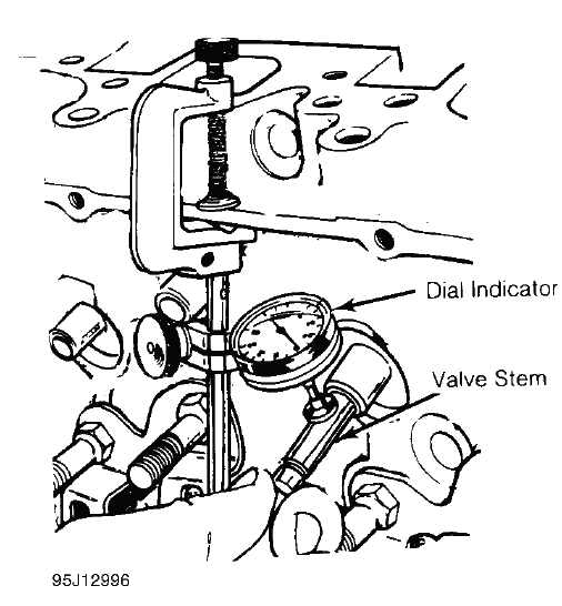
Fig. 6: Measuring Valve Stem-to-Guide Clearance
Lower valve approximately 1/16" below valve seat. Push valve stem against valve guide as far as possible.
Adjust dial indicator to zero. Push valve stem in opposite direction and note reading. Clearance must be within specification.
If valve guide clearance exceeds specification, valves with oversize stems may be used and valve guides are reamed to larger size or valve guide must be replaced. On some applications, a false guide is installed, then reamed to proper specification. Valve guide reamer set is used to ream valve guide to obtain proper clearance for new valve.
Reaming Valve Guide
Select proper reamer for size of valve stem. Reamer must be of proper length to provide clean cut through entire length of valve guide. Install reamer in valve guide and rotate to cut valve guide. See Fig. 7.
.png)
Fig. 7: Reaming Valve Guides
Replacing Valve Guide
Replace valve guide if clearance exceeds specification. Valve guides are either pressed, hammered or shrunk in place, depending upon cylinder head design and type of metal used.
Remove valve guide from cylinder head by pressing or tapping on a stepped drift. See Fig. 8. Once valve guide is installed, distance from cylinder head to top of valve guide must be checked. This distance must be within specification.
Aluminum heads are often heated before installing valve guide. Valve guide is sometimes cooled in dry ice prior to installation. Combination of a heated cylinder head and cooled valve guide ensures a tight guide fit upon assembly. The new guide must be reamed to specification.
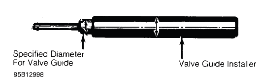
Fig. 8: Typical Valve Guide Remover & Installer
READ NEXT:
 Valves & Valve Seats
NOTE: Examples used in this article are general in nature and do not
necessarily relate
to a specific engine or system. Illustrations and procedures have been chosen
to guide mechanic through engine
Cylinder Head Reassembly
NOTE: Examples used in this article are general in nature and do not
necessarily relate
to a specific engine or system. Illustrations and procedures have been chosen
to guide mechanic through engine
Rocker Arms & Assemblies
NOTE: Examples used in this article are general in nature and do not
necessarily relate
to a specific engine or system. Illustrations and procedures have been chosen
to guide mechanic through engine
SEE MORE:
Description
ENGINE LUBRICATION SYSTEM DESCRIPTION - HYDRAULIC CIRCUIT
Overview
The lubrication method is a pressurized circulation type and it employs the
full-flow filtering system. In the
full-flow filtering system, all the oil supplied to the engine by the oil pump
normally passes through the oil
filter. I
DTC U1280 (Keyless Access Backup Control Unit) B-CAN Communication
Bus Line Error (BUS-OFF)
DTC (Backup Control Unit)
NOTE: If you are troubleshooting multiple DTCs, be sure to
follow the instructions in B-CAN System Diagnosis Test Mode A - Refer to: Body
Electrical Troubleshooting - B-CAN System Diagnosis Test Mode A - Initial
Communication and DTC Checks.
1. Problem verification.
C
