Honda HR-V: Wheel Alignment Theory & Operation
* PLEASE READ THIS FIRST *
NOTE: This is GENERAL information. This article is not intended to be specific to any unique situation or individual vehicle configuration. For model-specific information see appropriate articles where available.
PRE-ALIGNMENT INSTRUCTIONS
NOTE: This is GENERAL information. This article is not intended to be specific to any unique situation or individual vehicle configuration. For model-specific information see appropriate articles where available.
GENERAL ALIGNMENT CHECKS
Before adjusting wheel alignment, check the following:
- Each axle uses tires of same construction and tread style, equal in tread wear and overall diameter. Verify that radial and axial runout is not excessive. Inflation should be at manufacturer's specifications.
- Steering linkage and suspension must not have excessive play. Check for wear in tie rod ends and ball joints. Springs must not be sagging. Control arm and strut rod bushings must not have excessive play. See Fig. 1.
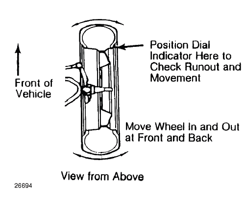
Fig. 1: Checking Steering Linkage
- Vehicle must be on level floor with full fuel tank, no passenger load, spare tire in place and no load in trunk. Bounce front and rear end of vehicle several times. Confirm vehicle is at normal riding height.
- Steering wheel must be centered with wheels in straight ahead position. If required, shorten one tie rod adjusting sleeve and lengthen opposite sleeve (equal amount of turns). See Fig. 2.
- Wheel bearings should have the correct preload and lug nuts must be tightened to manufacturer's specifications. Adjust camber, caster and toe-in using this sequence. Follow instructions of the alignment equipment manufacturer.
CAUTION: DO NOT attempt to correct alignment by straightening parts. Damaged parts MUST be replaced.
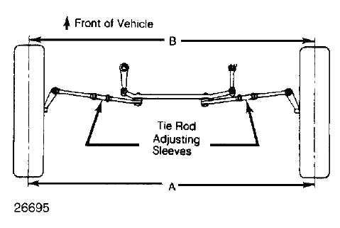
Fig. 2: Adjusting Tie Rod Sleeves (Top View)
ADJUSTMENTS
NOTE: This is GENERAL information. This article is not intended to be specific to any unique situation or individual vehicle configuration. For model-specific information see appropriate articles where available.
CAMBER
1. Camber is the tilting of the wheel, outward at either top or bottom, as viewed from front of vehicle. See Fig. 3.
2. When wheels tilts outward at the top (from centerline of vehicle), camber is positive. When wheels tilt inward at top, camber is negative. Amount of tilt is measured in degrees from vertical.
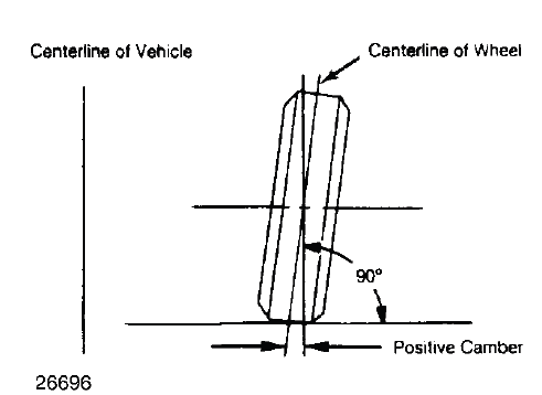
Fig. 3: Determining Camber Angle
CASTER
1. Caster is tilting of front steering axis either forward or backward from vertical, as viewed from side of vehicle. See Fig. 4.
2. When axis is tilted backward from vertical, caster is positive. This creates a trailing action on front wheels. When axis is tilted forward, caster is negative, causing a leading action on front wheels.
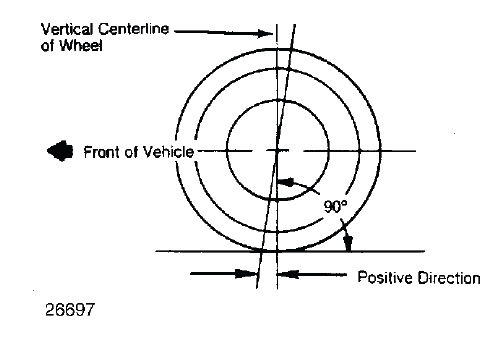
Fig. 4: Determining Caster Angle
TOE-IN ADJUSTMENT
Toe-in is the width measured at the rear of the tires subtracted by the width measured at the front of the tires at about spindle height. A positive figure would indicate toe-in and a negative figure would indicate toe-out. If the distance between the front and rear of the tires is the same, toe measurement would be zero. To adjust:
1) Measure toe-in with front wheels in straight ahead position and steering wheel centered. To adjust toe-in, loosen clamps and turn adjusting sleeve or adjustable end on right and left tie rods. See Fig. 2 and Fig. 5.
2) Turn equally and in opposite directions to maintain steering wheel in centered position. Face of tie rod end must be parallel with machined surface of steering rod end to prevent binding.
3) When tightening clamps, make certain that clamp bolts are positioned so there will be no interference with other parts throughout the entire travel of linkage.

Fig. 5: Wheel Toe-In (Dimension A Less Dimension B)
TOE-OUT ON TURNS
1. Toe-out on turns (turning radius) is a check for bent or damaged parts, and not a service adjustment. With caster, camber, and toe-in properly adjusted, check toe-out with weight of vehicle on wheels.
2. Use a full floating turntable under each wheel, repeating test with each wheel positioned for right and left turns. Incorrect toe-out generally indicates a bent steering arm. Replace arm, if necessary, and recheck wheel alignment.
STEERING AXIS INCLINATION
1. Steering axis inclination is a check for bent or damaged parts, and not a service adjustment. Vehicle must be level and camber should be properly adjusted. See Fig. 6.
2. If camber cannot be brought within limits and steering axis inclination is correct, steering knuckle is bent.
If camber and steering axis inclination are both incorrect by approximately the same amount, the upper and lower control arms are bent.
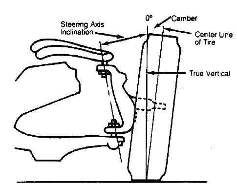
Fig. 6: Checking Steering Axis Inclination
READ NEXT:
 Maintenance
MAINTENANCE MAIN ITEMS (KA/KC MODELS)
If the message "SERVICE" does not appear more than 12 months after the
display is reset, change the
engine oil every year.
NOTE:
Independent of the maintenance
Emissions Maintenance Reminder
NOTE: To determine the appropriate reset procedure, refer to EMISSIONS
MAINTENANCE REMINDER RESET INDEX.
EMISSIONS MAINTENANCE REMINDER RESET INDEX
EMISSIONS MAINTENANCE REMINDER RESET - PROCEDURE 1
SEE MORE:
DTC Troubleshooting 25-120: Yaw Rate Sensor (Inside of
Modulator-Control Unit) Stuck
NOTE:
Before you troubleshoot, review the general troubleshooting information.
The yaw rate-acceleration sensor is built into the VSA modulator-control
unit.
Before troubleshooting, check the VSA modulator-control unit for proper
mounting. Improper mounting
of the VSA modulator-control unit
Front Door Panel Removal and Installation
Removal & Installation
1. Mirror Mount Cover - Remove
Remove the mirror mount cover (A).
2. Front Door Panel - Remove
Remove the cap (A) by tilting down the hook (B) with a flat-tip
screwdriver.
Remove the screws.
Open the cap (A), then remove the screw.
Start at the bottom e
