Honda HR-V: Connecting Rod Bearing Replacement
Honda HR-V (2015-2021) Service Manual / Engine / Engine Control System & Engine Mechanical - Service Information / Connecting Rod Bearing Replacement
Replacement
1. Engine/Transmission - Remove
2. Transmission - Remove
- Remove the transmission:
- M/T
- CVT
3. Pressure Plate, Clutch Disc, and Flywheel - Remove (M/T)
4. Drive Plate - Remove (CVT)
5. Connecting Rod Cap and Bearing Half - Remove
NOTE: Do not remove the lower block.
6. Connecting Rod Bearing Clearance - Inspect
.png)
- Clean the connecting rod journal and the connecting rod bearing half with a clean shop towel
- Place one strip of plastigage across the rod journal
- Line up the mark (A) on the connecting rod and the connecting rod cap,
then
reinstall the connecting rod bearing half and the connecting rod cap and the
connecting rod bolts finger-tight.
NOTE :- Apply new engine oil to the bolt threads and flanges.
- Do not rotate the crankshaft during inspection.
- Torque the connecting rod bolts to 20 N.m (2.0 kgf.m, 15 lbf.ft).
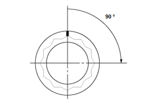
- Tighten the connecting rod bolts an additional 90º.
.png)
- Remove the connecting rod cap and the connecting rod bearing half, and measure the widest part of the plastigage.
Standard (New): 0.024-0.042 mm (0.00094-0.00165 in)
Service Limit: 0.055 mm (0.00217 in)
- If the plastigage measures too wide or too narrow, remove the upper half
of the connecting rod bearing.
Install a new, complete connecting rod bearing with the same color code, and recheck the clearance. Do not file, shim, or scrape the connecting rod bearings or the connecting rod caps to adjust clearance.
- If the plastigage shows the clearance is still incorrect, try the next larger or smaller connecting rod bearing (the color listed above or below that one), and check the clearance again. If the proper clearance cannot be obtained by using the appropriate larger or smaller connecting rod bearings, replace the crankshaft and start over.
7. Connecting Rod Bearing - Select
Big End Bore Code Locations
.png)
Connecting Rod Journal Code Locations
.png)
.png)
- Inspect each connecting rod for cracks and heat damage
- Numbers have been stamped on the side of each connecting rod as a code
for the size of the big end. Use them, and the letters stamped on the
crankshaft (codes for rod journal size), to choose the correct connecting
rod
bearings.
NOTE :- If the codes are indecipherable because of an accumulation of dirt and dust, do not scrub them with a wire brush or scraper. Clean them only with solvent or detergent.
- Each connecting rod falls into one of four tolerance ranges (from 0 to 0.024 mm (0.00095 in), in 0.006 mm (0.00024 in) increments) depending on the size of its big end bore. It is then stamped with a number (1, 2, 3, or 4) indicating the range. You may find any combination of 1, 2, 3, or 4 in any engine.
Big End Bore Size: 48.0 mm (1.890 in)
- Use the big end bore codes and the connecting rod journal codes to
select appropriate replacement
connecting rod bearings from the following table.
NOTE:- Color code is on the edge of the bearing.
- When using bearing halves of different colors, it does not matter which color is used in the top or bottom.
8. All Removed Parts - Install
- Install the parts in the reverse order of removal.
NOTE: Inspect the diameter of each connecting rod bolt when you install the connecting rod caps.
READ NEXT:
 Crankshaft Main Bearing Replacement
Replacement
1. Engine/Transmission - Remove
2. Transmission - Remove
Remove the transmission:
M/T
CVT
3. Pressure Plate, Clutch Disc, and Flywheel - Remove (M/T)
4. Drive Plate - Remove (CV
Crankshaft Pulley Removal and Installation
Special Tools Required
Holder Handle
07JAB-001020B
Pulley Holder
Attachment, 50 x
39 mm 07MABPY30100
Socket, 19 mm
07JAA-001020A
or equivalent
Removal
1. Right Front Wheel - Remove
2. Right Front S
Crankshaft and CKP Pulse Plate Removal, Installation, and Inspection
Special Tools Required
Driver Handle, 15
x 135L
07749-0010000
Bearing Driver
Attachment, 24 x
26 mm
07746-0010700
Removal
1. Engine/Transmission - Remove
2. Transmission - Remove
Remove the transm
SEE MORE:
Playing a USB Flash Drive
Your audio system reads and plays sound files on a USB flash drive in either
MP3,
WMA or AAC*1 format.
Connect your USB flash drive to the USB port, then select the USB mode.
*1: Only AAC format files recorded with iTunes are playable on this unit.
*2: Some or all of the lists may not be displaye
DTC B1931 Backup Control Unit No Response
DTC (Backup Control Unit)
NOTE: If you are troubleshooting multiple DTCs, be sure to follow the
instructions in B-CAN System
Diagnosis Test Mode A - Refer to: Body Electrical Troubleshooting - B-CAN System
Diagnosis Test Mode
A - Initial Communication and DTC Checks.
1. Problem verification.
Cl
© 2019-2026 Copyright www.hohrv2.com
