Honda HR-V: EGR Function Testing
TEST 1
1980-87 (PORTED EGR VALVE)
Check vacuum hoses for correct routing. Disconnect vacuum hose from EGR valve. Run engine to operating temperature. Apply 6 in. Hg to EGR valve. Ensure engine runs roughly or dies. Reconnect vacuum hose.
VACUUM CONTROL
EGR valve is controlled by a combination of either coolant temperature switch, speed sensor, vacuum solenoid, vacuum valves and computer. If further testing is required, see appropriate MITCHELLÂ IMPORTED CARS, LIGHT TRUCKS & VANS ENGINE PERFORMANCE SERVICE & REPAIR manual.
1. Disconnect vacuum hose from EGR valve and connect vacuum gauge to hose. Push a voltmeter positive probe into the terminal at the control box connector (Blue/Yellow on Accord). Connect the negative probe to ground. Jack up the front of the vehicle.
2. Support with safety stands, block rear wheels, and set hand brake. Start and warm up engine (cooling fan must come on). On Accord, remove control box from firewall and remove cover attaching screws. On all models, vacuum and voltage should be as follows:
EGR SYSTEM TEST
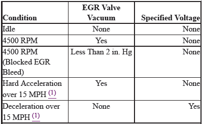
(1) In second gear or "2".
3. If voltage is available in the first 3 conditions, check thermosensor for continuity. There should be no continuity. If it has continuity, replace and retest. If there is no continuity, remove the control switch, disconnect the lower hose from control switch and connect a vacuum gauge to the hose. There should be no vacuum at idle.
4. If there is no vacuum, replace the control switch and retest. If there is vacuum, check for voltage at the Yellow/Black wire to the control switch solenoid valve (ignition ON). If there is no voltage, replace the control switch solenoid valve and retest. If there is voltage, replace the speed sensor and retest.
5. If there is no voltage available but there is vacuum for the first condition or vacuum is is greater than 2 in.Hg (50 mmHg) for the third condition, replace the EGR control valve and check vacuum hose routing.
If voltage is available for the fourth condition replace the control switch. If there is no voltage available for the fifth condition, check control switch.
6. With speed sensor jumpered and engine at idle, remove vacuum line at control switch and check for vacuum. If vacuum is available, reconnect line and check for voltage at Blue/Yellow wire at EGR solenoid valve A. There should be no voltage. If there is no voltage, replace control switch and retest.
7. If there is no vacuum available and no voltage for the second and fourth conditions, check for ported vacuum at 4500 RPM at EGR control solenoid valve A inlet. If vacuum is not available, check vacuum line routing and carburetor port. Clean and retest.
8. If vacuum is available, replace EGR control solenoid valve A. If vacuum and voltage are available for the fifth condition, replace EGR control solenoid valve A.
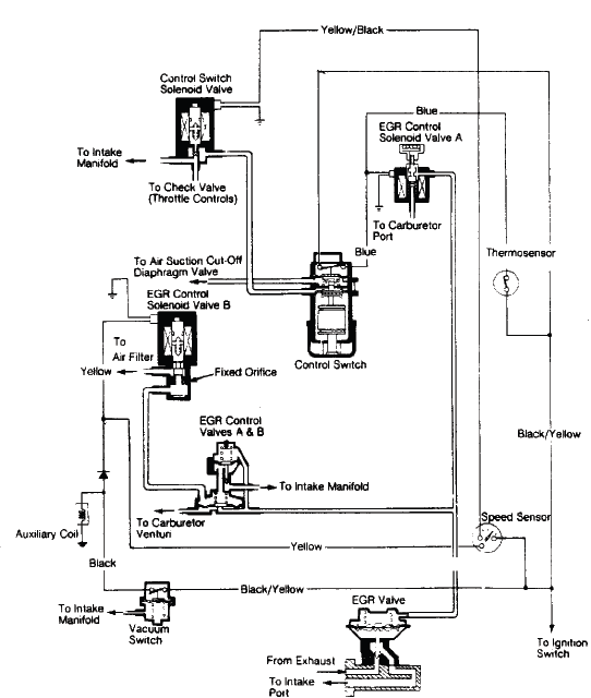
Fig. 1: Exhaust Gas Recirculation System (Accord)
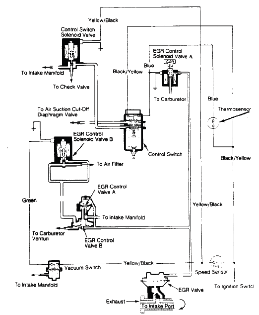
Fig. 2: Exhuaust Gas Recirculation System (Civic)
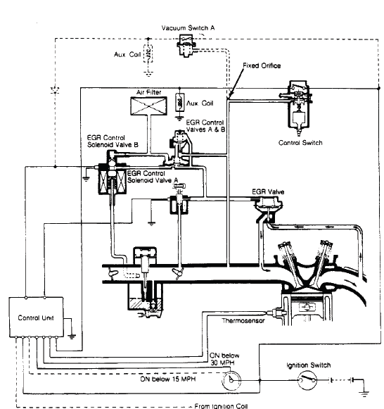
Fig. 3: Exhaust Gas Recirculation System (Prelude)
TEST 2
1988-96 (PORTED EGR VALVE)
1. Warm engine to normal operating temperature. Operate engine at idle. Attach a vacuum gauge to EGR vacuum hose. Locate EGR vacuum solenoid.
2. Using a jumper wire, ground signal wire from ECM to EGR vacuum solenoid. Vacuum should be present at EGR vacuum hose. On some models, engine speed may have to be increased 3000-4000 RPM.
3. Connect a hand-held vacuum pump to EGR valve. Start engine. Apply vacuum to EGR valve. If engine runs rough or stalls, and gauge holds vacuum, EGR valve is functioning properly.
TEST 3
1. Warm engine to normal operating temperature. Operate engine at idle. Attach a vacuum gauge to EGR vacuum hose. Locate EGR vacuum solenoid.
2. Using a jumper wire, ground signal wire from ECM to EGR vacuum solenoid. Vacuum should be present at EGR vacuum hose. On some models, engine speed may have to be increased 3000-4000 RPM.
3. Connect a hand-held vacuum pump to EGR valve. Start engine. Apply vacuum to EGR valve. If engine runs rough or stalls, and gauge holds vacuum, EGR valve is functioning properly.
TEST 4
1. Start and operate engine at idle. Disconnect vacuum hose from EGR valve. Connect vacuum pump/gauge to hose. If vacuum is present, go to next step. If vacuum is not present, go to step 4).
2. Disconnect 2-pin connector EGR control solenoid control box. Check for vacuum at EGR hose. If vacuum is not present, go to next step. If vacuum is present, check vacuum hose routing. If vacuum hose routing is okay, replace EGR control solenoid valve.
3. Turn ignition off. Unplug ECM connector "A". Check for continuity between EGR control solenoid valve 2-pin connector terminal No. 2 (Red wire) and ground. If continuity is present, repair short in wire between ECM terminal A16 and EGR control solenoid valve. If continuity is not present, replace ECM and retest system.
4. Turn ignition off. Unplug 3-pin connector from EGR valve lift sensor. Turn ignition on. Measure voltage between harness connector terminals No. 2 (Green/Blue wire) and No. 3 (Yellow/Blue wire). Voltage reading should be about 5 volts. If voltage reading is as specified, go to step 7. If voltage reading is not as specified, go to next step.
5. Measure voltage between EGR valve lift sensor terminal No. 3 (Yellow/Blue wire) and ground. Voltage reading should be about 5 volts. If voltage reading is as specified, repair open in wire between EGR valve lift sensor and ECM. If voltage reading is not as specified, go to next step.
6. Turn ignition off. Disconnect ECM connector "D". Using DVOM, check continuity between ECM connector terminal D21 and EGR valve lift sensor 3-pin connector terminal No. 3 (Yellow/Blue wire). If continuity is present, replace ECM. If continuity is not present, repair open in wire between EGR valve lift sensor and ECM.
7. Install vacuum pump/gauge to EGR valve. Reconnect ECM harness connectors. Start and operate engine at idle. Apply 8 in. Hg to EGR valve. If engine stalls or runs rough, go to next step. If engine idle quality does not change, replace EGR valve.
8. Turn ignition off. Unplug 2-pin connector from EGR control solenoid valve. Turn ignition on. Measure voltage between EGR control solenoid valve 2-pin connector terminal No. 1 (Black/Yellow wire) and ground. If battery voltage is present, go to next step. If battery voltage is not present, repair open in circuit between solenoid valve and ECM fuse No. 4 in passenger compartment fuse/relay block.
9. Install vacuum pump/gauge to vacuum hose from EGR valve. Start and operate engine at idle. Connect battery voltage to EGR control solenoid 2-pin connector terminal No. 1 (Black/Yellow wire). Connect a jumper between EGR control solenoid 2-pin connector terminal No. 2 (Red wire) and ground. Check vacuum gauge. If 18 in. Hg is present within one second, go to step 11. If vacuum reading is not as specified, go to next step.
10. Check vacuum hose(s) for leaks, restrictions or misrouting. Repair as necessary. If hoses are okay, disconnect lower vacuum hose on EGR control solenoid valve and connect vacuum gauge to hose. Start and operate engine at idle. If 6-10 in. Hg is present, replace EGR control solenoid valve. If vacuum is not present, EGR vacuum control valve.
11. Turn ignition off. Reconnect EGR valve lift sensor connector. Reconnect vacuum pump/gauge to EGR valve. Turn ignition on. Measure voltage between ECM connector terminals No. D17 and D22. Voltage reading should be about 1.2 volts with no vacuum applied, and about 4.3 volts with vacuum applied. If voltage readings are as specified, go to next step. If voltage readings are not as specified, go to step 13.
12. Repair open or short in wire between EGR valve lift sensor and ECM terminal D17. If wire is okay, replace EGR valve.
13. Change vacuum readings. If voltage increases/decreases as vacuum is increased/decreased, go to next step. If voltage does not change or is inconsistent, replace EGR valve.
14. Reconnect EGR vacuum hose No. 16. Start and operate engine at idle. Jumper ECM connector terminals No. A12 and A16. If engine stalls or runs rough, replace ECM and retest system. If engine idle quality did not change, repair open in wire between EGR control solenoid and ECM terminal A16.
TEST 5
For EGR function testing, see appropriate article in ENGINE PERFORMANCE section of MITCHELL1Â PRO DEMAND electronic information product.
READ NEXT:
 Ignition System - Service Information
REMOVAL & INSTALLATION
IGNITION COIL AND SPARK PLUG REMOVAL AND INSTALLATION
Removal and Installation
1. Harness Cover - Remove
2. Ignition Coil - Remove
Fig. 1: Ignition Coil With Torque Specif
Ignition System - Inspection & Adjustment
INSPECTION & ADJUSTMENT
IGNITION TIMING INSPECTION
Inspection
1. HDS DLC - Connect
NOTE: For specific operations, refer to the user's manual that came with the
HDS. Make sure the
HDS is loaded wi
SEE MORE:
Electric Parking Brake Symptom Troubleshooting - Electric Parking Brake
Indicator Does Not Go OFF, And No DTCS Are Stored
1. DTC check.
Turn the vehicle to the ON mode.
Check for DTCs with the HDS.
Are there DTCs indicated?
YES
Go to indicated DTC's troubleshooting.
NO
Go to step 2.
2. Gauge control module operation check.
Do the gauge control module self-diagnostic function.
Is the gauge control module OK?
YES
Troubleshooting
KEY INTERLOCK SYSTEM CIRCUIT TROUBLESHOOTING
NOTE: SRS components are located in this area. Review the SRS component
locations - Refer to: SRS
Component Location Index(KA/KC), or SRS Component Location Index(KA/KC), and
precautions and
procedures before doing repairs or servicing.
1. DTC check.
