Honda HR-V: Fog Lights
When the low beam headlights are on, turn the fog light switch on to use the fog lights.
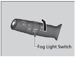
When the fog lights are on, the indicator in the instrument panel will be on.
The fog lights go off when the headlights turn off, or when the daytime running lights are on.
Daytime Running Lights
The headlights come on slightly dimmer than normal when the following conditions have been met:
- The ignition switch is in ON (II)*1.
- The headlight switch is off, or in
.png) .
. - The parking brake is released.
The lights remain on even if you set the parking brake. Turning off the ignition switch or setting the power mode to VEHICLE OFF will turn off the daytime running lights.
The headlights return to the original brightness once the headlight switch is turned on.
*1: Models with the smart entry system have an ENGINE START/STOP button instead of an ignition switch.
READ NEXT:
 Wipers and Washers
■Front Wiper/Washer
The windshield wipers and washers can be
used when the ignition switch is in ON (II)*1.
MIST
OFF
INT: Low speed with
intermittent
LO: Low speed wipe
HI: High speed wipe
Brightness Control
When the ignition switch is in ON (II)*1, you
can use the (select/reset) knob to
adjust
instrument panel brightness.
Brighten: Turn the knob to the right.
Dim: Turn the knob to the left.
You will h
Adjusting the Mirrors
Interior Rearview Mirror
Adjust the angle of the rearview mirror when you are sitting in the correct
driving
position.
■Rearview Mirror with Day and Night Positions
Flip the tab to switch the posit
SEE MORE:
Fastening a Seat Belt
After adjusting a front seat to the proper position, and while sitting
upright and well
back in the seat:
1. Pull the seat belt out slowly.
2. Insert the latch plate into the buckle, then
tug on the belt to make sure the buckle is
secure.
Make sure that the belt is not twisted or
caught on anyt
PGM-FI System Description - Components (KA/KC)
FUEL FILL CAP
FUEL TANK VAPOR/LIQUID
SEPARATION VALVE
FUEL TANK
FUEL PRESSURE REGULATOR
FUEL PUMP
FUEL FILTER
AIR FUEL RATIO (A/F) SENSOR
(SENSOR 1)
WARM UP THREEWAY CATALYTIC
CONVERTER (WU-TWC)
UNDER-FLOOR THREEWAY
CATALYTIC CONVERTER (UNDERFLOOR
TWC)
SECONDARY HEATED OXYGEN
SENSO
© 2019-2026 Copyright www.hohrv2.com
