Honda HR-V: Knock Sensor Removal and Installation
Honda HR-V (2015-2021) Service Manual / Engine / Engine Control System & Engine Mechanical - Service Information / Knock Sensor Removal and Installation
Removal & Installation
1. Intake Manifold - Remove
2. Knock Sensor - Remove
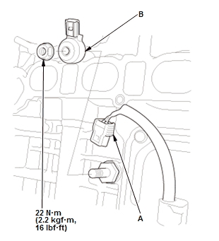
Fig. 28: Knock Sensor Location With Torque Specifications
- Disconnect the connector (A)
- Remove the knock sensor (B).
3. All Removed Parts - Install
- Install the parts in the reverse order of removal.
NOTE: When installing the knock sensor, make sure the direction of the sensor connector is facing up.
MAF SENSOR/IAT SENSOR REMOVAL AND INSTALLATION
Removal & Installation
1. MAF Sensor/IAT Sensor - Remove
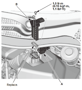
- Disconnect the connector (A)
- Remove the MAF sensor/IAT sensor (B).
2. All Removed Parts - Install
- Install the parts in the reverse order of removal with a new O-ring.
MAP SENSOR REMOVAL AND INSTALLATION
Removal & Installation
1. MAP Sensor - Remove
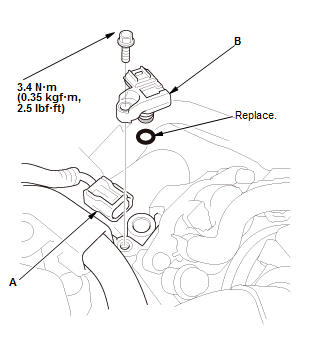
- Disconnect the connector (A)
- Remove the MAP sensor (B).
2. All Removed Parts - Install
Install the parts in the reverse order of removal with a new O-ring.
OUTPUT SHAFT (COUNTERSHAFT) SPEED SENSOR REMOVAL AND INSTALLATION
Removal & Installation
1. Engine Undercover (2WD) - Remove
2. Output Shaft (Countershaft) Speed Sensor - Remove
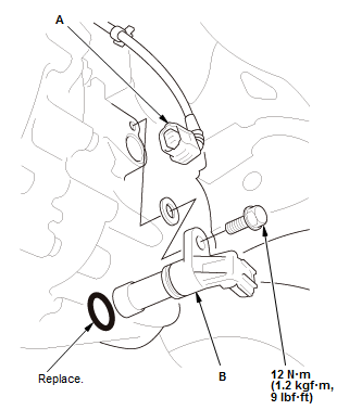
- Disconnect the connector (A)
- Remove the output shaft (countershaft) speed sensor (B).
3. All Removed Parts - Install
- Install the parts in the reverse order of removal with a new O-ring.
READ NEXT:
 PCM Removal and Installation
Removal
NOTE:
Make sure the HDS or the MVCI has the latest HDS software version.
If you are replacing the PCM after substituting a known-good PCM,
reinstall the original PCM, then do
this proced
Piston, Ring, Pin, and Connecting Rod Removal and Installation
Removal
1. Crankshaft - Remove
2. Oil Jet - Remove
3. Metal or Hard Carbon - Remove
If you can feel a ridge of metal or hard carbon around the top of each
cylinder,
remove it with a ridge reamer
Pulley End Crankshaft Oil Seal Replacement - In Car
Special Tools Required
Driver Handle, 15
x 135L
07749-0010000
Hub
Dis/Assembly
Tool, 42 mm
07GAF-SD40200
Replacement
1. Oil Pump - Remove
2. Pulley End Crankshaft Oil Seal - Remove
3. Pulley End Cr
SEE MORE:
DTC Troubleshooting 52-11: Motor Stuck OFF
NOTE: Before you troubleshoot, review the general troubleshooting
information.
DTCs (VSA)
1. Solenoid operation check:
Turn the vehicle to the ON mode.
Clear the DTC with the HDS.
Turn the vehicle to the OFF (LOCK) mode, then to the ON mode.
Operate any one of the four solenoids in the VSA FU
Towing a Trailer
Your vehicle is not designed to tow a trailer. Attempting to do so can void
your
warranties.
Towing Your Vehicle
Continuously variable transmission models
Your vehicle is not designed to be towed behind a motorhome. If your vehicle
needs
to be towed in an emergency, refer to the emergency towing i
© 2019-2026 Copyright www.hohrv2.com
