Honda HR-V: Piston, Ring, Pin, and Connecting Rod Removal and Installation
Removal
1. Crankshaft - Remove
2. Oil Jet - Remove
3. Metal or Hard Carbon - Remove
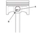
- If you can feel a ridge of metal or hard carbon around the top of each cylinder, remove it with a ridge reamer (A). Follow the reamer manufacturer's instructions. If the ridge is not removed, it may damage the piston as it is pushed out.
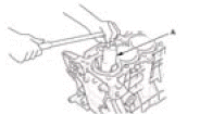
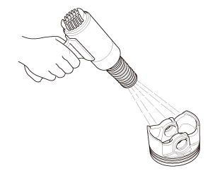
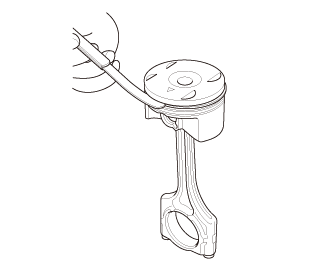
4. Piston/Connecting Rod Assembly - Remove
- Use the wooden handle of a hammer (A) to drive out the piston/connecting
rod
assembly (B).
NOTE : Take care not to damage the cylinder with the connecting rod - Reinstall the connecting rod bearings and the connecting rod caps after
removing
each piston/connecting rod assembly.
NOTE :- Mark each piston/connecting rod assembly with its cylinder number to make sure they are reinstalled in the original order.
- The existing number on the connecting rod does not indicate its position in the engine, it indicates the rod bore size.
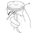
5. Piston Ring - Remove
- Using a ring expander (A), remove the old piston rings (B)
- Clean all ring grooves thoroughly with a squared-off broken ring or a
ring groove cleaner
with a blade to fit the piston grooves. File down the blade, if necessary.
The top ring and second
ring grooves are 1.2 mm (0.047 in) wide, and the oil ring groove is 2.0 mm
(0.079 in) wide. Do
not use a wire brush to clean the ring grooves, or cut the ring grooves
deeper with the cleaning
tool.
NOTE : If the piston is to be separated from the connecting rod, do not install new rings yet.
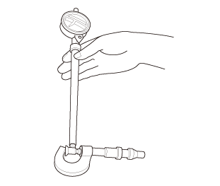
6. Piston Ring End Gap - Inspect
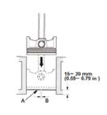
- Using a piston, push a new ring (A) into the cylinder bore 15-20 mm (0.59-0.79 in) from the bottom
- Measure the piston ring end-gap (B) with a feeler gauge:
- If the gap is too small, check to see if you have the proper rings for your engine.
- If the gap is too large, recheck the cylinder bore diameter against the wear limits. If the bore is beyond the service limit, the engine block must be rebored.
Top Ring
Standard (New): 0.200-0.350 mm (0.008- 0.013 in)
Service Limit: 0.6 mm (0.024 in)
Second Ring
Standard (New): 0.400-0.550 mm (0.016- 0.021 in)
Service Limit: 0.7 mm (0.028 in)
Oil Ring (TEIKOKU and UNITED)
Standard (New): 0.20-0.70 mm (0.008-0.027 in)
Service Limit: 0.8 mm (0.031 in)
Oil Ring (RIKEN and ALLIED)
Standard (New): 0.20-0.50 mm (0.008-0.019 in)
Service Limit: 0.55 mm (0.021 in)
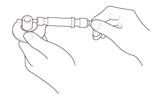
7. Piston Pin - Remove
- Apply new engine oil to the piston pin snap rings (A), and turn them in
the ring
grooves until the end gaps are lined up with the cutouts in the piston pin
bores
(B).
NOTE: Take care not to damage the ring grooves.
- Remove the snap rings (A) from both sides of each piston. Start at the cutout in the piston pin bore. Remove the snap rings carefully so they do not go flying or get lost. Wear eye protection.
- Separately heat each piston and connecting rod assembly to about 158ºF (70ºC)
- Remove the piston pin.
8. Piston Pin - Inspect
- Measure the diameter of the piston pin.
Standard (New): 19.960-19.964 mm (0.78583-0.78598 in)
Service Limit: 19.96 mm (0.7858 in)
- Zero the dial indicator to the piston pin diameter.
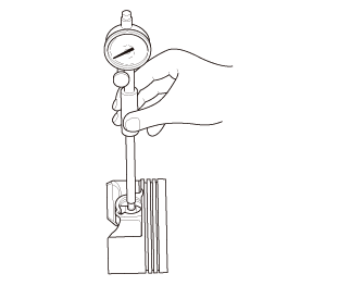
- Check the difference between the piston pin diameter and the piston pin hole diameter in the piston.
Standard (New): -0.004-0.003 mm (-0.00016-0.00012 in)
Service Limit: 0.006 mm (0.00024 in)
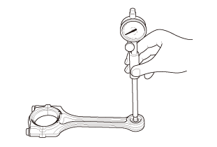
- Measure the piston pin-to-connecting rod clearance.
Standard (New): 0.005-0.015 mm (0.00020-0.00059 in)
Service Limit: 0.02 mm (0.0008 in)
- Measure the connecting rod small end bore diameter.
Standard (New): 19.969-19.975 mm (0.78618-0.78642 in)
Installation
1. Piston Pin - Install
- Install a piston pin snap ring (A) only on one side
- Coat the piston pin bore in the piston, the bore in the connecting rod, and the piston pin with new engine oil.
- Heat the piston to about 158ºF (70ºC).
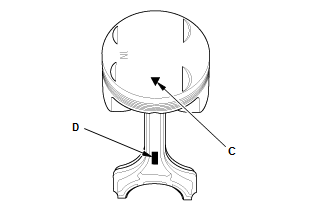
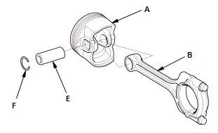
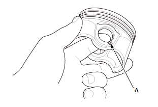
- Assemble the piston (A) and the connecting rod (B) with the arrow (C) and the embossed mark (D) on the same side. Install the piston pin (E)
- Install the remaining snap ring (F).
NOTE : Turn the snap rings in the ring grooves until the end gaps are positioned at the bottom of the piston - Reassemble the other pistons the same way.
2. Piston Ring - Install
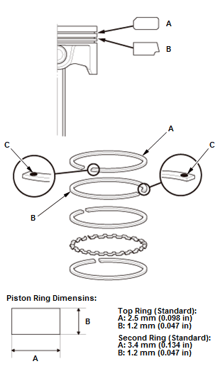
Fig. 30: Piston Ring Exploded View With Dimension Specifications
- Install the piston rings as shown. The top ring (A) has a U, 1A, 1R, or 1T mark, and the second ring (B) has a 2A, 2R, or 2T mark. The manufacturing marks (C) must be facing upward.
- After installing a new set of rings, measure the ring-to-groove clearances.
Top Ring
Standard (New): 0.045-0.070 mm (0.002 in)
Service Limit: 0.13 mm (0.005 in)
Second Ring (TEIKOKU)
Standard (New): 0.035-0.060 mm (0.002 in)
Service Limit: 0.13 mm (0.005 in)
Second Ring (RIKEN and ALLIED)
Standard (New): 0.030-0.055 mm (0.002 in)
Service Limit: 0.125 mm (0.004 in)
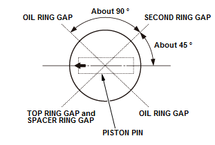
Fig. 31: Piston Ring Positioning Chart
- Rotate the rings in their grooves to make sure they do not bind
- Position the ring end gaps as shown.
3. Piston/Connecting Rod Assembly - Install
- Remove the connecting rod caps. Check that the bearing is securely in place
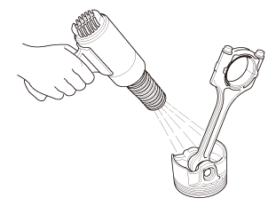
- Apply new engine oil to the piston, inside of the ring compressor, and the cylinder bore, then attach the ring compressor to the piston/connecting rod assembly
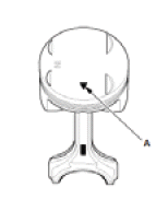
- Position the piston/connecting rod assembly with the arrow (A) facing the cam chain side of the engine block.
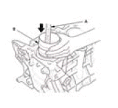
- Position the piston/connecting rod assembly in the cylinder, and tap it in using the wooden handle of a hammer (A). Maintain downward force on the ring compressor (B) to prevent the rings from expanding before entering the cylinder bore
- Stop after the ring compressor pops free, and check the connecting rod-to-rod journal alignment before pushing the piston into place.
4. Oil Jet - Install
5. Crankshaft - Install
READ NEXT:
 Pulley End Crankshaft Oil Seal Replacement - In Car
Special Tools Required
Driver Handle, 15
x 135L
07749-0010000
Hub
Dis/Assembly
Tool, 42 mm
07GAF-SD40200
Replacement
1. Oil Pump - Remove
2. Pulley End Crankshaft Oil Seal - Remove
3. Pulley End Cr
Rocker Arm Assembly Removal and Installation
Removal
1. Cylinder Head Cover - Remove
2. Rocker Arm Assembly - Remove
Loosen the locknuts and the adjusting screws (A).
Fig. 32: Lost Motion Holder Bolt Removal Sequence
Remove the lost motio
Throttle Body Removal and Installation
Removal
Do not insert your fingers into the installed throttle body when you turn the
vehicle to the ON mode, or while
the vehicle is in ON mode. If you do, you will seriously injure your fingers if
SEE MORE:
Interpreting A Current Controlled Pattern
NOTE: Current controlled drivers are also known as "Peak and Hold"
drivers. They
typically require injector circuits with a total leg resistance with less than
12
ohm.
NOTE: This example is based on a constant power/switched ground circuit.
See Fig. 3 for pattern that the following text describe
DTC B1C68, Driver's Heater Not Heating
DTC (Front Seat Heater Control Unit)
NOTE :
If you are troubleshooting multiple DTCs, be sure to follow the
instructions in B-CAN System Diagnosis
Test Mode A - Refer to: Body Electrical Troubleshooting - B-CAN System
Diagnosis Test Mode A -
Initial Communication and DTC Checks.
The seat h
