Honda HR-V: Overview of DVOM
A DVOM is typically used to check injector resistance and available voltage at the injector. Some techs also use it check injector on-time either with a built-in feature or by using the dwell/duty function.
There are situations where the DVOM performs these checks dependably, and other situations where it can deceive you. It is important to be aware of these strengths and weaknesses. We will cover the topics above in the following text.
Checking Injector Resistance
If a short in an injector coil winding is constant, an ohmmeter will accurately identify the lower resistance. The same is true with an open winding. Unfortunately, an intermittent short is an exception. A faulty injector with an intermittent short will show "good" if the ohmmeter cannot force the short to occur during testing.
Alcohol in fuel typically causes an intermittent short, happening only when the injector coil is hot and loaded by a current high enough to jump the air gap between two bare windings or to break down any oxides that may have formed between them.
When you measure resistance with an ohmmeter, you are only applying a small current of a few milliamps. This is nowhere near enough to load the coil sufficiently to detect most problems. As a result, most resistance checks identify intermittently shorted injectors as being normal.
There are two methods to get around this limitation. The first is to purchase an tool that checks injector coil windings under full load. The Kent-Moore J-39021 is such a tool, though there are others. The Kent-Moore costs around $240 at the time of this writing and works on many different manufacturer's systems.
The second method is to use a lab scope. Remember, a lab scope allows you to see the regular operation of a circuit in real time. If an injector is having an short or intermittent short, the lab scope will show it.
Checking Available Voltage At the Injector
Verifying a fuel injector has the proper voltage to operate correctly is good diagnostic technique. Finding an open circuit on the feed circuit like a broken wire or connector is an accurate check with a DVOM.
Unfortunately, finding an intermittent or excessive resistance problem with a DVOM is unreliable.
Let's explore this drawback. Remember that a voltage drop due to excessive resistance will only occur when a circuit is operating? Since the injector circuit is only operating for a few milliseconds at a time, a DVOM will only see a potential fault for a few milliseconds. The remaining 90+% of the time the unloaded injector circuit will show normal battery voltage.
Since DVOMs update their display roughly two to five times a second, all measurements in between are averaged. Because a potential voltage drop is visible for such a small amount of time, it gets "averaged out", causing you to miss it.
Only a DVOM that has a "min-max" function that checks EVERY MILLISECOND will catch this fault consistently (if used in that mode). The Fluke 87 among others has this capability.
A "min-max" DVOM with a lower frequency of checking (100 millisecond) can miss the fault because it will probably check when the injector is not on. This is especially true with current controlled driver circuits. The Fluke 88, among others fall into this category.
Outside of using a Fluke 87 (or equivalent) in the 1 mS "min-max" mode, the only way to catch a voltage drop fault is with a lab scope. You will be able to see a voltage drop as it happens.
One final note. It is important to be aware that an injector circuit with a solenoid resistor will always show a voltage drop when the circuit is energized. This is somewhat obvious and normal; it is a designed-in voltage drop. What can be unexpected is what we already covered--a voltage drop disappears when the circuit is unloaded. The unloaded injector circuit will show normal battery voltage at the injector. Remember this and do not get confused.
Checking Injector On-Time With Built-In Function
Several DVOMs have a feature that allows them to measure injector on-time (mS pulse width). While they are accurate and fast to hookup, they have three limitations you should be aware of:
- They only work on voltage controlled injector drivers (e.g "Saturated Switch"), NOT on current controlled injector drivers (e.g. "Peak & Hold").
- A few unusual conditions can cause inaccurate readings.
- Varying engine speeds can result in inaccurate readings.
Regarding the first limitation, DVOMs need a well-defined injector pulse in order to determine when the injector turns ON and OFF. Voltage controlled drivers provide this because of their simple switch-like operation. They completely close the circuit for the entire duration of the pulse. This is easy for the DVOM to interpret.
The other type of driver, the current controlled type, start off well by completely closing the circuit (until the injector pintle opens), but then they throttle back the voltage/current for the duration of the pulse. The DVOM understands the beginning of the pulse but it cannot figure out the throttling action. In other words, it cannot distinguish the throttling from an open circuit (de-energized) condition.
Yet current controlled injectors will still yield a millisecond on-time reading on these DVOMs. You will find it is also always the same, regardless of the operating conditions. This is because it is only measuring the initial completely-closed circuit on-time, which always takes the same amount of time (to lift the injector pintle off its seat). So even though you get a reading, it is useless.
The second limitation is that a few erratic conditions can cause inaccurate readings. This is because of a DVOM's slow display rate; roughly two to five times a second. As we covered earlier, measurements in between display updates get averaged. So conditions like skipped injector pulses or intermittent long/short injector pulses tend to get "averaged out", which will cause you to miss important details.
The last limitation is that varying engine speeds can result in inaccurate readings. This is caused by the quickly shifting injector on-time as the engine load varies, or the RPM moves from a state of acceleration to stabilization, or similar situations. It too is caused by the averaging of all measurements in between DVOM display periods. You can avoid this by checking on-time when there are no RPM or load changes.
A lab scope allows you to overcome each one of these limitations.
Checking Injector On-Time With Dwell Or Duty
If no tool is available to directly measure injector millisecond on-time measurement, some techs use a simple DVOM dwell or duty cycle functions as a replacement.
While this is an approach of last resort, it does provide benefits. We will discuss the strengths and weaknesses in a moment, but first we will look at how a duty cycle meter and dwell meter work.
How A Duty Cycle Meter and Dwell Meter Work
All readings are obtained by comparing how long something has been OFF to how long it has been ON in a fixed time period. A dwell meter and duty cycle meter actually come up with the same answers using different scales. You can convert freely between them. See RELATIONSHIP BETWEEN DWELL & DUTY CYCLE READINGS TABLE.
The DVOM display updates roughly one time a second, although some DVOMs can be a little faster or slower.
All measurements during this update period are tallied inside the DVOM as ON time or OFF time, and then the total ratio is displayed as either a percentage (duty cycle) or degrees (dwell meter).
For example, let's say a DVOM had an update rate of exactly 1 second (1000 milliseconds). Let's also say that it has been measuring/tallying an injector circuit that had been ON a total of 250 mS out of the 1000 mS. That is a ratio of one-quarter, which would be displayed as 25% duty cycle or 15º dwell (six-cylinder scale). Note that most duty cycle meters can reverse the readings by selecting the positive or negative slope to trigger on. If this reading were reversed, a duty cycle meter would display 75%.
Strengths of Dwell/Duty Meter
The obvious strength of a dwell/duty meter is that you can compare injector on-time against a known-good reading. This is the only practical way to use a dwell/duty meter, but requires you to have known-good values to compare against.
Another strength is that you can roughly convert injector mS on-time into dwell reading with some computations.
A final strength is that because the meter averages everything together it does not miss anything (though this is also a severe weakness that we will look at later). If an injector has a fault where it occasionally skips a pulse, the meter registers it and the reading changes accordingly.
Let's go back to figuring out dwell/duty readings by using injector on-time specification. This is not generally practical, but we will cover it for completeness. You NEED to know three things:
- Injector mS on-time specification.
- Engine RPM when specification is valid.
- How many times the injectors fire per crankshaft revolution.
The first two are self-explanatory. The last one may require some research into whether it is a bank-fire type that injects every 360º of crankshaft rotation, a bank-fire that injects every 720º, or an SFI that injects every 720º. Many manufacturers do not release this data so you may have to figure it out yourself with a frequency meter.
Here are the four complete steps to convert millisecond on-time:
1. Determine the injector pulse width and RPM it was obtained at. Let's say the specification is for one millisecond of on-time at a hot idle of 600 RPM.
2. Determine injector firing method for the complete 4 stroke cycle. Let's say this is a 360º bank-fired, meaning an injector fires each and every crankshaft revolution.
3. Determine how many times the injector will fire at the specified engine speed (600 RPM) in a fixed time period. We will use 100 milliseconds because it is easy to use. Six hundred crankshaft Revolutions Per Minute (RPM) divided by 60 seconds equals 10 revolutions per second. Multiplying 10 times.100 yields one; the crankshaft turns one time in 100 milliseconds. With exactly one crankshaft rotation in 100 milliseconds, we know that the injector fires exactly one time.
4. Determine the ratio of injector on-time vs. off-time in the fixed time period, then figure duty cycle and/or dwell. The injector fires one time for a total of one millisecond in any given 100 millisecond period. One hundred minus one equals 99. We have a 99% duty cycle. If we wanted to know the dwell (on 6 cylinder scale), multiple 99% times.6; this equals 59.4º dwell.
Weaknesses of Dwell/Duty Meter
The weaknesses are significant. First, there is no one-to-one correspondence to actual mS on-time. No manufacturer releases dwell/duty data, and it is time-consuming to convert the mS on-time readings. Besides, there can be a large degree of error because the conversion forces you to assume that the injector(s) are always firing at the same rate for the same period of time. This can be a dangerous assumption.
Second, all level of detail is lost in the averaging process. This is the primary weakness. You cannot see the details you need to make a confident diagnosis.
Here is one example. Imagine a vehicle that has a faulty injector driver that occasionally skips an injector pulse.
Every skipped pulse means that that cylinder does not fire, thus unburned O2 gets pushed into the exhaust and passes the O2 sensor. The O2 sensor indicates lean, so the computer fattens up the mixture to compensate for the supposed "lean" condition.
A connected dwell/duty meter would see the fattened pulse width but would also see the skipped pulses. It would tally both and likely come back with a reading that indicated the "pulse width" was within specification because the rich mixture and missing pulses offset each other.
This situation is not a far-fetched scenario. Some early GM 3800 engines were suffering from exactly this. The point is that a lack of detail could cause misdiagnosis.
As you might have guessed, a lab scope would not miss this.
RELATIONSHIP BETWEEN DWELL & DUTY CYCLE READINGS
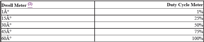
(1) These are just some examples for your understanding. It is okay to fill
in the gaps.
(2) Dwell meter on the six-cylinder scale.
READ NEXT:
 The Two Types of Injector Drivers
NOTE: This is GENERAL information. This article is not intended to be
specific to any
unique situation or individual vehicle configuration. For model-specific
information see appropriate a rtic
Interpreting A Voltage Controlled Pattern
NOTE: Voltage controlled drivers are also known as "Saturated Switch"
drivers. They
typically require injector circuits with a total leg resistance of 12 ohms or
more.
NOTE: This example is based on
SEE MORE:
Key Types and Functions
All the keys have an immobilizer system. The
immobilizer system helps to protect against vehicle
theft.
The keys contain precision electronics.
Adhere to the following advice to prevent damage to
the electronics:
Do not leave the keys in direct sunlight, or in
locations with high temperature or
DTC U3003-17 (EPS Control Unit)
NOTE: Before you troubleshoot, review the general troubleshooting
information.
DTC (EPS)
1. Problem verification.
Turn the vehicle to the ON mode.
Clear the DTC with the HDS.
Clear DTCs
Turn the vehicle to the OFF (LOCK) mode, then start the engine.
Turn the steering wheel to left and right
