Honda HR-V: The Two Types of Injector Drivers
NOTE: This is GENERAL information. This article is not intended to be specific to any unique situation or individual vehicle configuration. For model-specific information see appropriate a rticles where available.
OVERVIEW
There are two types of transistor driver circuits used to operate electric fuel injectors: voltage controlled and current controlled. The voltage controlled type is sometimes called a "saturated switch" driver, while the current controlled type is sometimes known as a "peak and hold" driver.
The basic difference between the two is the total resistance of the injector circuit. Roughly speaking, if a particular leg in an injector circuit has total resistance of 12 or more ohms, a voltage control driver is used. If less than 12 ohms, a current control driver is used.
It is a question of what is going to do the job of limiting the current flow in the injector circuit; the inherent "high" resistance in the injector circuit, or the transistor driver. Without some form of control, the current flow through the injector would cause the solenoid coil to overheat and result in a damaged injector.
VOLTAGE CONTROLLED CIRCUIT ("SATURATED SWITCH")
The voltage controlled driver inside the computer operates much like a simple switch because it does not need to worry about limiting current flow. Recall, this driver typically requires injector circuits with a total leg resistance of 12 or more ohms.
The driver is either ON, closing/completing the circuit (eliminating the voltage-drop), or OFF, opening the circuit (causing a total voltage drop).
Some manufacturers call it a "saturated switch" driver. This is because when switched ON, the driver allows the magnetic field in the injector to build to saturation. This is the same "saturation" property that you are familiar with for an ignition coil.
There are two ways "high" resistance can be built into an injector circuit to limit current flow. One method uses an external solenoid resistor and a low resistance injector, while the other uses a high resistance injector without the solenoid resistor. See the left side of Fig. 1.
In terms of injection opening time, the external resistor voltage controlled circuit is somewhat faster than the voltage controlled high resistance injector circuit. The trend, however, seems to be moving toward use of this latter type of circuit due to its lower cost and reliability. The ECU can compensate for slower opening times by increasing injector pulse width accordingly.
NOTE: Never apply battery voltage directly across a low resistance injector. This will cause injector damage from solenoid coil overheating.
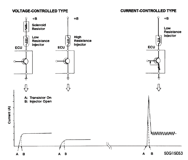
Fig. 1: Injector Driver Types - Current and Voltage
CURRENT CONTROLLED CIRCUIT ("PEAK & HOLD")
The current controlled driver inside the computer is more complex than a voltage controlled driver because as the name implies, it has to limit current flow in addition to its ON-OFF switching function. Recall, this driver typically requires injector circuits with a total leg resistance of less than 12 ohms.
Once the driver is turned ON, it will not limit current flow until enough time has passed for the injector pintle to open. This period is preset by the particular manufacturer/system based on the amount of current flow needed to open their injector. This is typically between two and six amps. Some manufacturers refer to this as the "peak" time, referring to the fact that current flow is allowed to "peak" (to open the injector).
Once the injector pintle is open, the amp flow is considerably reduced for the rest of the pulse duration to protect the injector from overheating. This is okay because very little amperage is needed to hold the injector open, typically in the area of one amp or less. Some manufacturers refer to this as the "hold" time, meaning that just enough current is allowed through the circuit to "hold" the already-open injector open.
There are a couple methods of reducing the current. The most common trims back the available voltage for the circuit, similar to turning down a light at home with a dimmer.
The other method involves repeatedly cycling the circuit ON-OFF. It does this so fast that the magnetic field never collapses and the pintle stays open, but the current is still significantly reduced. See the right side of Fig. 1 for an illustration.
The advantage to the current controlled driver circuit is the short time period from when the driver transistor goes ON to when the injector actually opens. This is a function of the speed with which current flow reaches its peak due to the low circuit resistance. Also, the injector closes faster when the driver turns OFF because of the lower holding current.
NOTE: Never apply battery voltage directly across a low resistance injector. This will cause injector damage from solenoid coil overheating.
THE TWO WAYS INJECTOR CIRCUITS ARE WIRED
NOTE: This is GENERAL information. This article is not intended to be specific to any unique situation or individual vehicle configuration. For model-specific information see appropriate articles where available.
Like other circuits, injector circuits can be wired in one of two fundamental directions. The first method is to steadily power the injectors and have the computer driver switch the ground side of the circuit. Conversely, the injectors can be steadily grounded while the driver switches the power side of the circuit.
There is no performance benefit to either method. Voltage controlled and current controlled drivers have been successfully implemented both ways.
However, 95% percent of the systems are wired so the driver controls the ground side of the circuit. Only a handful of systems use the drivers on the power side of the circuit. Some examples of the latter are the 1970's Cadillac EFI system, early Jeep 4.0 EFI (Renix system), and Chrysler 1984-87 TBI.
READ NEXT:
 Interpreting A Voltage Controlled Pattern
NOTE: Voltage controlled drivers are also known as "Saturated Switch"
drivers. They
typically require injector circuits with a total leg resistance of 12 ohms or
more.
NOTE: This example is based on
Interpreting A Current Controlled Pattern
NOTE: Current controlled drivers are also known as "Peak and Hold"
drivers. They
typically require injector circuits with a total leg resistance with less than
12
ohm.
NOTE: This example is based on
SEE MORE:
Rear Seat Disassembly And Reassembly
Disassembly & Reassembly
1. Rear Seat - Remove
2. Rear Seat - Disassemble
Remove the head restraint
Remove the recline upper cover (A).
NOTE : The illustration shows a left
rear seat. Do the same procedure for the right rear seat.
Remove the center cover (A).
Fig. 1: Rear Seat Back A
Cylinder Head Assembly - Inspection & Adjustment
INSPECTION & ADJUSTMENT
CYLINDER HEAD INSPECTION FOR WARPAGE
Inspection
1. Cylinder Head - Remove
2. Cylinder Head Warpage - Inspect
Check the cylinder head for warpage. Measure along
the edges, and three ways across the center:
If warpage is less than 0.08 mm (0.0031 in)
cylinder head
