Honda HR-V: Rocker Arm Assembly Removal and Installation
Removal
1. Cylinder Head Cover - Remove
2. Rocker Arm Assembly - Remove
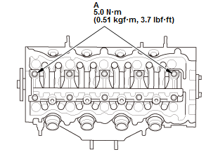
- Loosen the locknuts and the adjusting screws (A).
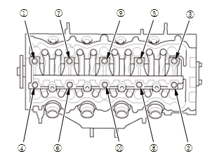
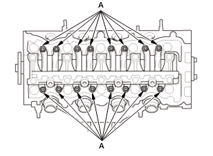
Fig. 32: Lost Motion Holder Bolt Removal Sequence
- Remove the lost motion holder bolts. To prevent damaging the lost motion holder and the rocker shaft
- loosen the bolts, in sequence, two turns at a time.
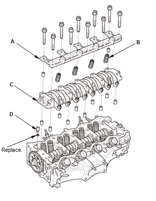
- Remove the lost motion holder (A) and the lost motion assemblies (B)
- Remove the rocker arm assembly (C)
- Remove the oil control orifice (D).
Installation
1. Rocker Arm Assembly - Reassemble
- If the rocker arm assembly is disassembled, reassemble the rocker arm assembly.
2. Rocker Arm Assembly - Install
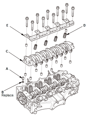
- Install the oil control orifice (A) with a new O-ring (B)
- Install the rocker arm assembly (C)
- Install the lost motion assembles (D) and the lost motion holder (E).
NOTE : Apply new engine oil to the lost motion assembly.
- Tighten the two lost motion holder bolts (A).
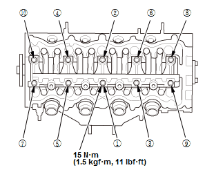
Fig. 33: Lost Motion Holder Tightening Sequence With Torque Specifications
- Tighten each bolts two turns at a time in sequence.
3. Valve Clearance - Adjust
4. Cylinder Head Cover - Install
ROCKER ARM OIL CONTROL VALVE REMOVAL AND INSTALLATION
Removal & Installation
1. Rocker Arm Oil Control Valve - Remove
With rocker arm oil pressure switch or rocker arm oil pressure sensor
Without rocker arm oil pressure switch or rocker arm oil pressure sensor
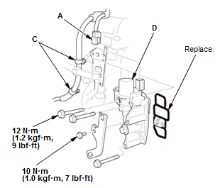
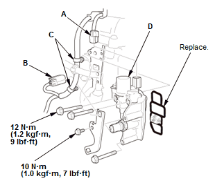
- Disconnect the connector (A)
- With rocker arm oil pressure switch or rocker arm oil pressure sensor: Disconnect the connector (B)
- Remove the harness clamps (C)
- Remove the rocker arm oil control valve (D).
2. All Removed Parts - Install
- Install the parts in the reverse order of removal with a new O-ring.
ROCKER ARM OIL PRESSURE SWITCH REMOVAL AND INSTALLATION (KA/KC)
Removal & Installation
1. Rocker Arm Oil Pressure Switch - Remove
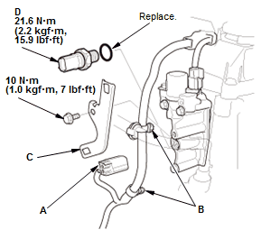
Fig. 34: Rocker Arm Oil Pressure Exploded View With Torque Specifications
- Disconnect the connector (A)
- Remove the harness clamps (B)
- Remove the bracket (C)
- Remove the rocker arm oil pressure switch (D).
2. All Removed Parts - Install
- Install the parts in the reverse order of removal with a new O-ring.
SECONDARY HO2S REMOVAL AND INSTALLATION (KA/KC)
Special Tools Required
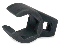
O2 Sensor Socket Wrench Snap-on SWR2 or Snap-on YA8875, commercially available
Removal & Installation
1. Vehicle - Lift
- Raise and support the vehicle.
2. Secondary HO2S - Remove
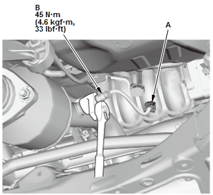
Fig. 35: Secondary HO2S With Torque Specifications
- Disconnect the connector (A)
- Remove secondary HO2S (B).
3. All Removed Parts - Install
- Install the parts in the reverse order of removal.
READ NEXT:
 Throttle Body Removal and Installation
Removal
Do not insert your fingers into the installed throttle body when you turn the
vehicle to the ON mode, or while
the vehicle is in ON mode. If you do, you will seriously injure your fingers if
Transmission End Crankshaft Oil Seal Replacement - In Car
Special Tools Required
Driver Handle, 15
x 135L
07749-0010000
Oil Seal Driver
Attachment, 96
mm 07ZADPNAA100
Replacement
1. Transmission - Remove
Remove the transmission:
M/T
CVT
2. Press
Valve Guide Replacement
Special Tools Required
Valve Guide
Driver, 5.35 x 9.7
mm
07742-0010100
Valve Guide
Reamer, 5.5 mm
07HAH-PJ7A100
Replacement
1. Valve, Valve Seal, and Valve Spring Seat - Remove
2. Valve Guide - Remo
SEE MORE:
Keyless Access Control Unit Removal and Installation
Removal & Installation
NOTE: If the keyless access control unit is replaced, do the keyless access
registration. If the original keyless
access control unit is installed, confirm that all systems work properly.
1. Gauge Control Module - Remove
2. Keyless Access Control Unit - Remove
Disconne
Climate Control Unit Removal and Installation
Removal & Installation
1. Switch Panel - Remove
2. Glove Box - Remove
3. Climate Control Unit - Remove
Pull the climate control unit (A)
Remove the clip (B)
Disconnect the connector (C)
Disconnect the connector (D) (Dual A/C type).
Remove the climate control unit (A).
4. All Removed P
