Honda HR-V: Valve Guide Replacement
Honda HR-V (2015-2021) Service Manual / Engine / Engine Control System & Engine Mechanical - Service Information / Valve Guide Replacement
Special Tools Required
Valve Guide Driver, 5.35 x 9.7 mm 07742-0010100
Valve Guide Reamer, 5.5 mm 07HAH-PJ7A100
Replacement
1. Valve, Valve Seal, and Valve Spring Seat - Remove
2. Valve Guide - Remove
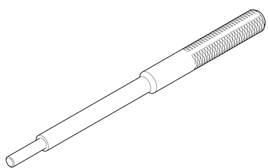
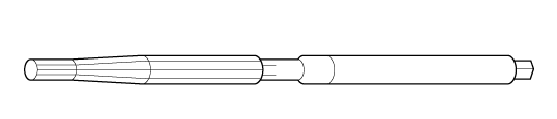
- As illustrated below, use a commercially available air-impact valve guide driver (A) modified to fit the diameter of the valve guides. In most cases, the same procedure can be done using the valve guide driver, 5.35 x 9.7 mm and a conventional hammer
- Select the proper replacement valve guides, and chill them in the freezer section of a refrigerator for at least an hour.
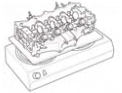
- Use a hot plate or an oven to evenly heat the cylinder head to 300ºF
(150ºC).
Monitor the temperature with a cooking thermometer. Do not get the cylinder head hotter than 300ºF (150ºC); excessive heat may loosen the valve seats.
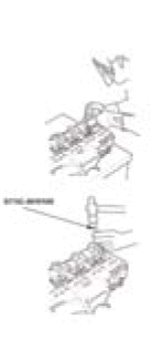
- Working from the camshaft side, use the valve guide driver and an air hammer to drive the valve guide about 2 mm (0.08 in) towards the combustion chamber. This will knock off some of the carbon and make removal easier. Hold the air hammer directly in line with the valve guide to prevent damaging the driver. Wear safety goggles or a face shield
- Turn the cylinder head over, and drive the valve guide out toward the camshaft side of the cylinder head
- If a valve guide will not move, drill it out with an 8 mm (5/16 in)
drill bit, then try
again.
NOTE : Drill guides only in extreme cases; you could damage the cylinder head if the valve guide breaks.
3. Valve Guide - Install
- Take out a new valve guide(s) from the freezer, one at a time, as you need them
- Apply a thin coat of new engine oil to the outside of a new valve guide
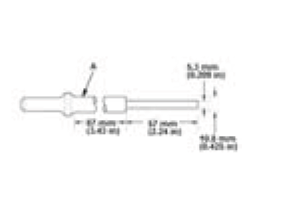
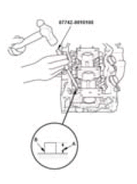
- Install the valve guide from the camshaft side of the cylinder head; use the valve guide driver to drive the valve guide into the specified installed height (A) of the valve guide (B). If you have all 16 valve guides to do, you may have to reheat the cylinder head.
18.25-18.75 mm (0.7185-0.7382 in)
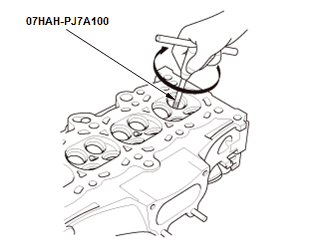
- Coat both the valve guide reamer, 5.5 mm and the valve guide with cutting oil
- Rotate the valve guide reamer clockwise the full length of the valve guide bore
- Continue to rotate the valve guide reamer clockwise while removing it from the bore
- Thoroughly wash the valve guide in detergent and water to remove any cutting residue.
4. Valve Stem-to-Guide Clearance - Inspect
NOTE: Verify that a valve slides into the intake and exhaust valve guides without sticking.
5. Valve Seat - Inspect
NOTE: If necessary renew the valve seat using a valve seat cutter.
6. All Removed Parts - Install
- Install the parts in the reverse order of removal.
READ NEXT:
 Valve, Spring, and Valve Seal Removal and Installation
Special Tools Required
Valve Spring
Compressor
Attachment
07757-PJ1010A
Stem Seal Driver
07PAD-0010000
Removal
NOTE: Identify the valves and the valve springs as they are removed so that
each item
SEE MORE:
DTC B12C7 Electric Steering Lock Motor Circuit Failure
DTC (Power Control Unit)
NOTE: If you are troubleshooting multiple DTCs, be sure to follow the
instructions in B-CAN System
Diagnosis Test Mode A - Refer to: Body Electrical Troubleshooting - B-CAN System
Diagnosis Test Mode
A - Initial Communication and DTC Checks.
1. Problem verification:
Cle
Steering Column - Inspection & Adjustment
DESCRIPTION
EPS SYSTEM DESCRIPTION - STEERING COLUMN
The steering force from the steering wheel is sent to the column shaft. The
torque sensor measures the
difference between the force applied to the column shaft and the resistance to
turning the wheels due to road
friction, and converts it to a v
© 2019-2026 Copyright www.hohrv2.com
