Honda HR-V: Transmission End Crankshaft Oil Seal Replacement - In Car
Honda HR-V (2015-2021) Service Manual / Engine / Engine Control System & Engine Mechanical - Service Information / Transmission End Crankshaft Oil Seal Replacement - In Car
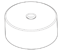
Special Tools Required
Driver Handle, 15 x 135L 07749-0010000
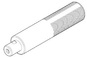
Oil Seal Driver Attachment, 96 mm 07ZADPNAA100
Replacement
1. Transmission - Remove
- Remove the transmission:
- M/T
- CVT
2. Pressure Plate, Clutch Disc, and Flywheel - Remove (M/T)
3. Drive plate - Remove (CVT)
4. Transmission End Crankshaft Oil Seal - Remove
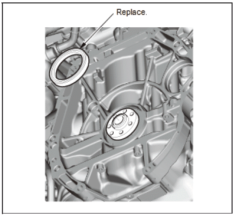
5. Transmission End Crankshaft Oil Seal - Install
- Clean and dry the transmission end crankshaft oil seal housing
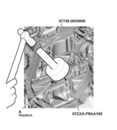
- Apply a light coat of new engine oil to the lip of a new transmission end crankshaft oil seal (A)
- Use the driver handle, 15 x 135L and the oil seal driver attachment, 96 mm to drive a new transmission end crankshaft oil seal squarely into the engine block to the specified installed height.
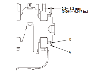
- Measure the distance between the engine block (A) and the transmission end crankshaft oil seal (B).
0.2-1.2 mm (0.008-0.047 in)
- Clean the excess oil off the crankshaft, and check that the transmission end crankshaft oil seal lip is not distorted.
6. All Removed Parts - Install
- Install the parts in the reverse order of removal.
UNDER-FLOOR TWC REMOVAL AND INSTALLATION (KA/KC)
Removal & Installation
NOTE: Unless otherwise indicated, illustrations used in the procedure are for 2WD.
1. Engine Undercover (2WD) - Remove
2. Secondary HO2S - Remove
3. Under-Floor TWC - Remove
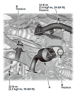
Fig. 37: Under Floor TWC Exploded View With Torque Specifications
- Remove the under-floor TWC (A) and the gaskets (B).
4. All Removed Parts - Install
- Install the parts in the reverse order of removal with new gaskets and nuts.
READ NEXT:
 Valve Guide Replacement
Special Tools Required
Valve Guide
Driver, 5.35 x 9.7
mm
07742-0010100
Valve Guide
Reamer, 5.5 mm
07HAH-PJ7A100
Replacement
1. Valve, Valve Seal, and Valve Spring Seat - Remove
2. Valve Guide - Remo
Valve, Spring, and Valve Seal Removal and Installation
Special Tools Required
Valve Spring
Compressor
Attachment
07757-PJ1010A
Stem Seal Driver
07PAD-0010000
Removal
NOTE: Identify the valves and the valve springs as they are removed so that
each item
SEE MORE:
Dashboard Side Lid Removal and Installation
Removal & Installation
NOTE : SRS components are located in this area. Review the SRS component
locations - Refer to: SRS
Component Location Index (KA/KC), or SRS Component Location Index (KA/KC) and
the precautions
and procedures before doing repairs or service.
Driver's Side
1. Dashboard Sid
DTC Troubleshooting C1110-96, C1111-96: Electric Parking Brake
Actuator Malfunction
NOTE: Before you troubleshoot, review the how to troubleshoot the
electric parking brake system.
1. Problem verification:
Turn the vehicle to the ON mode.
Clear the DTC with the HDS.
Turn the vehicle to the OFF (LOCK) mode, then to the ON mode.
Pull the electric parking brake switch to apply
© 2019-2026 Copyright www.hohrv2.com
