Honda HR-V: Shift Lever Disassembly and Reassembly (CVT)
Exploded View
1. Shift Lever Assembly - Exploded View
NOTE: Do not wipe off the special grease applied to the area of the shift lever marked with an asterisk (*).
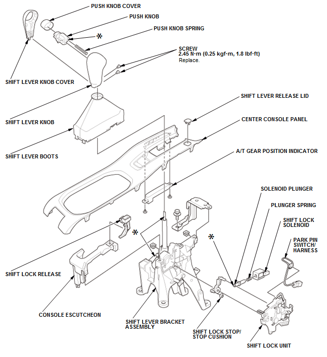
Fig. 55: Exploded View Of Shift Lever Assembly With Torque Specifications
Disassembly & Reassembly
SRS components are located in this area. Review the SRS component locations - Refer to: SRS Component Location Index (KA/KC), or SRS Component Location Index (KA/KC) and the precautions and procedures before doing repair or service.
1. Shift Lever Assembly - Remove
2. Shift Lock Unit - Remove
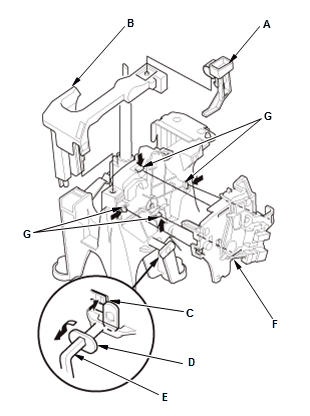
- Remove the shift lock release (A)
- Remove the console escutcheon (B)
- Release the lock tab (C) and turn the pivot pin (D) counterclockwise using a hex wrench (E) as shown, and pull it
- Remove the shift lock unit (F) while releasing the lock tabs (G).
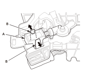
3. Shift Lock Solenoid - Remove
NOTE: Do not wipe off the special grease applied to the area of the shift lever marked with an asterisk (*).
- Pull the shift lock solenoid (A) out by expanding the lock tabs (B).

- Remove the shift lock solenoid (A).
NOTE: The shift lock solenoid consists of the solenoid (B), the solenoid plunger (C), and the plunger spring (D).
4. Shift Lock Stop/Stop Cushion - Remove
5. Park Pin Switch/Harness - Remove
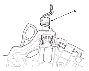
- Remove the park pin switch (A).
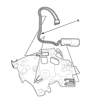
- Remove the park pin switch/harness (A).
6. All Removed Parts - Install
- Install the parts in the reverse order of removal.
READ NEXT:
 Transfer Assembly Disassembly and Reassembly (CVT)
Special Tools Required
Oil Seal Driver Attachment, 58 mm 07JAD-PH80101
Holder, Companion 07PAB-0020000
Driver, 32.5 mm 070AD-SAA0100
Driver Handle, 15 x 135L 07749-0010000
Exploded View
1. Transfe
Component Location Index
A/T GEAR POSITION INDICATOR COMPONENT LOCATION INDEX (CVT)
Without paddle shifter
With paddle shifter
A/T INTERLOCK SYSTEM COMPONENT LOCATION INDEX (CVT)
CVT DIFFERENTIAL COMPONENT LOCATION INDEX
How to Information
HOW TO TROUBLESHOOT THE CVT SYSTEM (CVT)
How to Check for DTCs with the Honda Diagnostic System (HDS)
When the powertrain control module (PCM) senses an abnormality in the input
or output systems, th
SEE MORE:
Traction Control, 4WD, & AWD
TRACTION CONTROL DISABLE
WARNING: Placing a non-compatible vehicle on a single-axle dynamometer
could result in
a safety hazard to technicians and damage to vehicle. Vehicles which use All-
Wheel Drive (AWD) or traction control may not be clearly marked. Use common
sense and take all necessary prec
HDS Does Not Communicate with AWD Control Unit (AWD)
Remedy
AWD System Symptom Troubleshooting - HDS does not communicate (AWD)
HDS DOES NOT COMMUNICATE WITH VEHICLE (AWD)
Remedy
Dlc Circuit Troubleshooting
REAR DIFFERENTIAL LEAKS FLUID (AWD)
Probable Cause
Fluid level too high
Clogged breather hose
Worn or damaged oil seal
Damaged sealing washer
