Honda HR-V: Final Drive Shaft Disassembly and Reassembly (CVT)
Honda HR-V (2015-2021) Service Manual / Transmission / Continuously Variable Transmission (CVT) - Testing & Troubleshooting / Disassembly and Reassembly / Final Drive Shaft Disassembly and Reassembly (CVT)
Special Tools Required
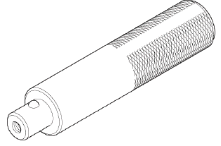
Driver Handle, 15 x 135L 07749-0010000
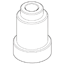
Attachment, 45 mm 07947-6890300
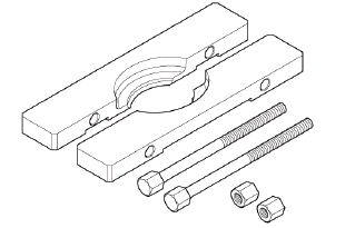
Bearing Separator 07KAF-PS30200
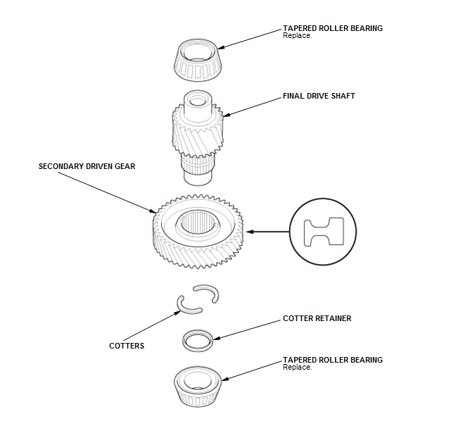
Exploded View
1. Final Drive Shaft - Exploded View
Disassembly
NOTE: The tapered roller bearing and the tapered roller bearing outer race should be replaced as a set.
1. Final Drive Shaft Tapered Roller Bearing - Remove
Transmission housing side
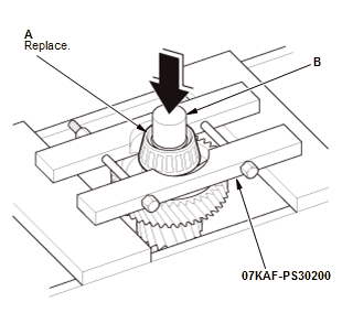
Torque converter housing side
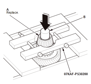
- Remove the tapered roller bearings (A) using the bearing separator and a press (B).
2. Secondary Driven Gear - Remove
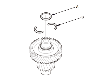
- Remove the cotter retainer (A) and the cotters (B).
- Remove the secondary driven gear (A) using a press.
Reassembly
NOTE:
- The tapered roller bearing and the tapered roller bearing outer race should be replaced as a set.
- Adjust the tapered roller bearing preload after replacing the tapered roller bearing and the tapered roller bearing outer race.
- Apply a light coat of clean transmission fluid on all parts before installation.
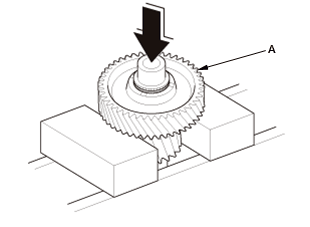
1. Secondary Driven Gear - Install
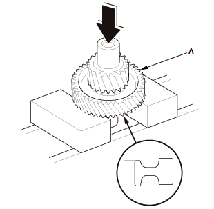
- Install the secondary driven gear (A) until it bottoms using a press as shown.
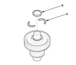
- Install the cotters (A) and the cotter retainer (B).
2. Final Drive Shaft Tapered Roller Bearing - Install
Transmission housing side
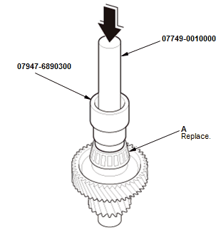
Torque converter housing side
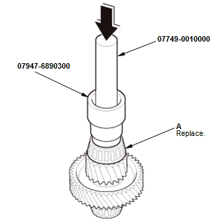
- Install the tapered roller bearings (A) until they bottom using the 15 x 135L driver handle, the 45 mm attachment, and a press.
READ NEXT:
 Shift Lever Disassembly and Reassembly (CVT)
Exploded View
1. Shift Lever Assembly - Exploded View
NOTE: Do not wipe off the special grease applied to the area of the shift
lever marked with an asterisk (*).
Fig. 55: Exploded View Of Shift Lev
Transfer Assembly Disassembly and Reassembly (CVT)
Special Tools Required
Oil Seal Driver Attachment, 58 mm 07JAD-PH80101
Holder, Companion 07PAB-0020000
Driver, 32.5 mm 070AD-SAA0100
Driver Handle, 15 x 135L 07749-0010000
Exploded View
1. Transfe
Component Location Index
A/T GEAR POSITION INDICATOR COMPONENT LOCATION INDEX (CVT)
Without paddle shifter
With paddle shifter
A/T INTERLOCK SYSTEM COMPONENT LOCATION INDEX (CVT)
CVT DIFFERENTIAL COMPONENT LOCATION INDEX
SEE MORE:
"D"
DCLV
Deceleration Valve
DCS
Deceleration Control System
DDI
Direct Diesel Injection
DFI
Direct Diesel Injection
DI
Direct Injection
DKV
Deceleration Kick Valve
DLCV
Deceleration Mixture Control Valve
DM-TL
Diagnostic Module Tank Leakage
DMS
Dual Manifold System
DOC
Diesel Oxidation Catalyst
DOHC
Dua
DTC B0050-13
NOTE:
Before doing this troubleshooting procedure, find out if the vehicle was
in a collision. If so, verify
that all the required components were replaced with new components, of the
correct part number,
and that they were properly installed.
Before doing this troubleshooting procedure, re
© 2019-2026 Copyright www.hohrv2.com
