Honda HR-V: Voltage Waveform Samples
NOTE: This is GENERAL information. This article is not intended to be specific to any unique situation or individual vehicle configuration. For model-specific information see appropriate articles where available.
EXAMPLE #1 - VOLTAGE CONTROLLED DRIVER
These two known-good waveform patterns are from a Ford 4.6L V8 VIN [W]. Fig. 18 illustrates the 64 volt inductive kick on this engine, indicating no clamping is occurring. The second pattern, Fig. 19, was taken during hot idle, closed loop, and no load.
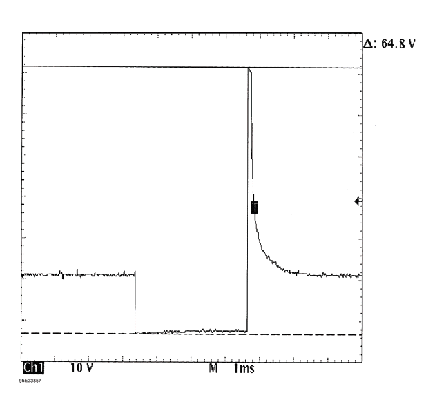
Fig. 18: Injector Bank - Known Good - Voltage Pattern
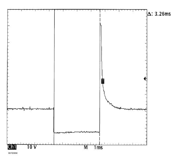
Fig. 19: Injector Bank - Known Good - Voltage Pattern
EXAMPLE #2 - VOLTAGE CONTROLLED DRIVER
The known-good waveform pattern in Fig. 20 is from a GM 3.8L V6 PFI VIN [3]. It was taken during hot idle, closed loop and no load.
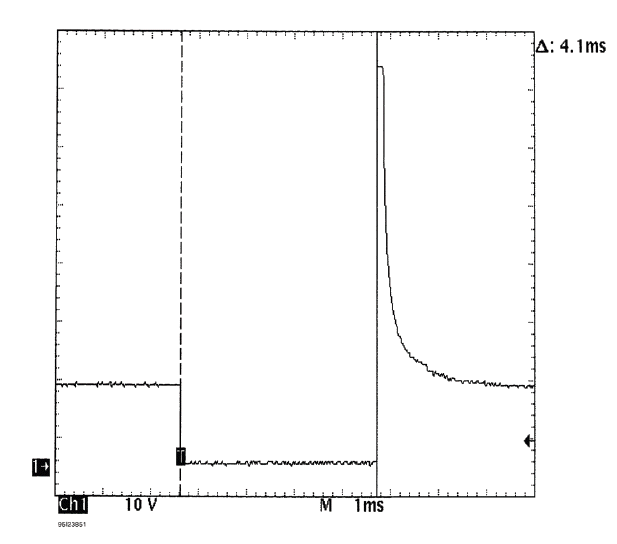
Fig. 20: Injector Bank - Known Good - Voltage Pattern
EXAMPLE #3 - VOLTAGE CONTROLLED DRIVER
This known-good waveform pattern, Fig. 21, is from a GM 5.0L V8 TPI VIN [F]. It was taken during hot idle, closed loop and no load.
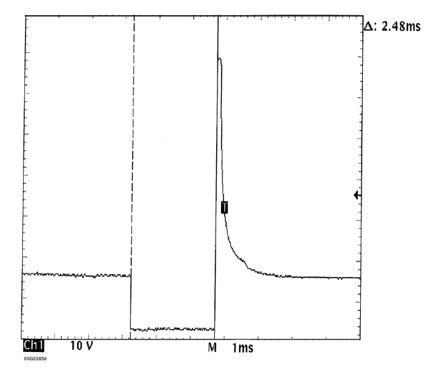
Fig. 21: Injector Bank - Known Good - Voltage Pattern
EXAMPLE #4 - CURRENT CONTROLLED DRIVER
From 1984 to 1987, Chrysler used this type injector drive on their TBI-equipped engines. See Fig. 22 for a known-good pattern. Instead of the ground side controlling the injector, Chrysler permanently grounds out the injector and switches the power feed side. Most systems do not work this way.
These injectors peak at 6 amps of current flow and hold at 1 amp.
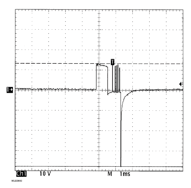
Fig. 22: Single Injector - Known Good - Voltage Pattern
EXAMPLE #5 - CURRENT CONTROLLED DRIVER
These two known-good waveform patterns are from a Chrysler 3.0L V6 VIN [3]. The first waveform, Fig. 23, is a dual trace pattern that illustrates how Chrysler uses the rising edge of the engine speed signal to trigger the injectors. The second waveform, Fig. 24, was taken during hot idle, closed loop, and no load.
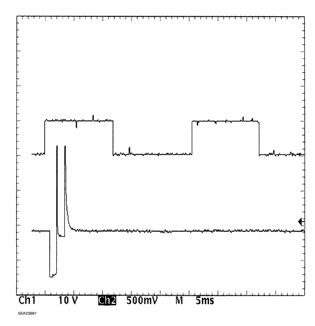
Fig. 23: Injector Bank - Known Good - Voltage Pattern
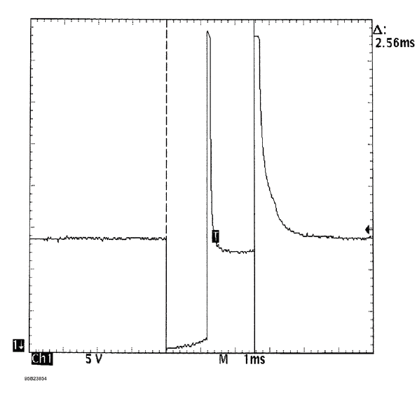
Fig. 24: Injector Bank - Known Good - Voltage Pattern
EXAMPLE #6 - CURRENT CONTROLLED DRIVER
This known-good pattern from a Ford 3.0L V6 PFI VIN [U] illustrates that a zener diode inside the computer is used to clamp the injector's inductive kick to 35-volts on this system. See Fig. 25.
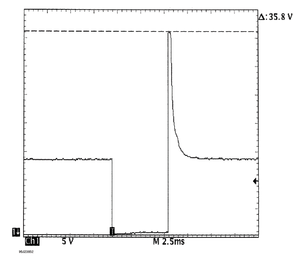
Fig. 25: Injector Bank - Known Good - Voltage Pattern
EXAMPLE #7 - CURRENT CONTROLLED DRIVER
This known-good waveform from a Ford 5.0L V8 CFI VIN [F] was taken during hot idle, closed loop, and no load. See Fig. 26.
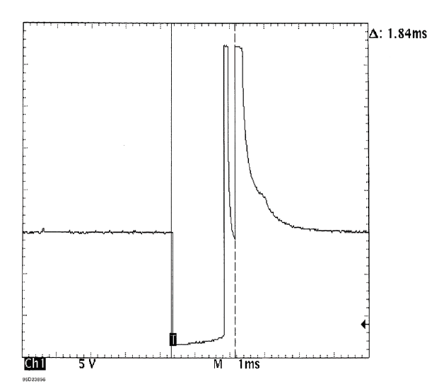
Fig. 26: Single Injector - Known Good - Voltage Pattern
EXAMPLE #8 - CURRENT CONTROLLED DRIVER
These two known-good waveform patterns are from a GM 2.0L In-Line 4 VIN [1]. Fig. 27 illustrates the 78 volt inductive spike that indicates a zener diode is not used. The second waveform, Fig. 28, was taken during hot idle, closed loop, and no load.
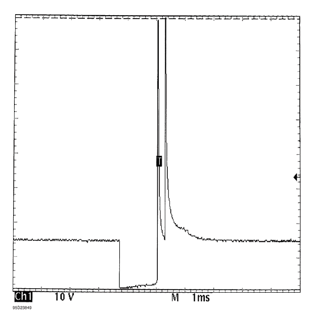
Fig. 27: Single Injector - Known Good - Voltage Pattern
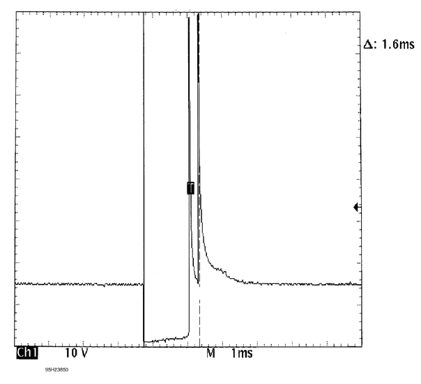
Fig. 28: Single Injector - Known Good - Voltage Pattern
READ NEXT:
 Wheel Alignment Theory & Operation
* PLEASE READ THIS FIRST *
NOTE: This is GENERAL information. This article is not intended to be
specific to any
unique situation or individual vehicle configuration. For model-specific
information s
Maintenance
MAINTENANCE MAIN ITEMS (KA/KC MODELS)
If the message "SERVICE" does not appear more than 12 months after the
display is reset, change the
engine oil every year.
NOTE:
Independent of the maintenance
SEE MORE:
Wiper Arm/Nozzle Adjustment
Adjustment
Windshield
1. Wiper Arm/Nozzle - Adjust
Adjust the washer nozzles by gently gripping, and then moving, the
outside of each nozzle (A).
Do not insert tools into the nozzle hole (B), as it may cause the washer
fluid to spray incorrectly.
Wiper Arms Auto-Stop Position
1. Turn the ve
Seat Heater Replacement
Replacement
NOTE : SRS components are located in this area. Review the SRS component
locations - Refer to: SRS
Component Location Index (KA/KC), or SRS Component Location Index (KA/KC) and
the precautions
and procedures before doing repairs or service.
Front Seat Cushion Heater
1. Front Seat Cushi
