Honda HR-V: Crankshaft and CKP Pulse Plate Removal, Installation, and Inspection
Special Tools Required
Driver Handle, 15 x 135L 07749-0010000
.png)
Bearing Driver Attachment, 24 x 26 mm 07746-0010700
.png)
Removal
1. Engine/Transmission - Remove
2. Transmission - Remove
- Remove the transmission:
- M/T
- CVT
3. Pressure Plate, Clutch Disc, and Flywheel - Remove (M/T)
4. Drive Plate - Remove (CVT)
5. Cylinder Head - Remove
6. Transmission End Crankshaft Oil Seal - Remove - Refer to: Pulley End Crankshaft Oil Seal Replacement - In Car, or Transmission End Crankshaft Oil Seal Replacement - In Car
7. Oil Pan - Remove
8. Engine Oil Strainer and Baffle Plate - Remove
.png)
9. Connecting Rod Cap and Bearing Half - Remove
.png)
NOTE: Keep all connecting rod caps and connecting rod bearings in order.
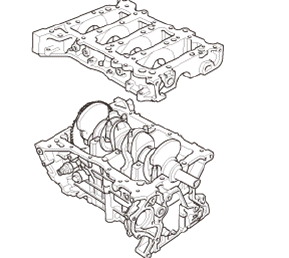
10. Lower Block - Remove
.png)
Fig. 6: Lower Block Removal Sequence
1. Remove the 8 mm bolts in the sequence shown.
.png)
Fig. 7: Main Cap Removal Sequence
2. Remove the bearing cap bolts. To prevent warpage, loosen the bolts in sequence 1/3 turn at a time; repeat the sequence until all bolts are loosened.
.png)
3. Using a flat blade screwdriver, separate the lower block from the engine block in the places shown.
.png)
4. Remove the lower block and the bearings.
NOTE: Keep all main bearings in order.
11. Crankshaft - Remove
.png)
1. Lift the crankshaft out of the engine block.
NOTE:
- Keep all the bearings in order.
- Be careful not to damage the journals and the CKP pulse plate (A).
2. Remove the thrust washers.
12. CKP Pulse Plate - Remove
.png)
NOTE: Be careful not to damage the CKP pulse plate.
Inspection
1. Crankshaft - Inspect
.png)
Journal Diameter, Out-of-Round, and Taper
- Clean the crankshaft oil passages with pipe cleaners or a suitable brush
- Check the keyway slot and the threaded holes for damage
- Measure the out-of-round at the middle of each rod and main journal in two places. The difference between measurements on each journal must not be more than the service limit.
Standard (New): 54.976-55.000 mm (2.16441-2.16535 in)
Standard (New): 44.976-45.000 mm (1.77071-1.77165 in)
Standard (New): 0.005 mm (0.00020 in) max.
Service Limit: 0.01 mm (0.0004 in)
- Measure the taper at the edges of each rod and the main journal. The difference between measurements on each journal must not be more than the service limit.
Standard (New): 0.005 mm (0.00020 in) max.
Service Limit: 0.01 mm (0.0004 in)
.png)
Straightness
- Place the V-blocks on a flat surface
- Check the total runout with the crankshaft supported on V-blocks
- Measure the runout on all of the main journals. Rotate the crankshaft two complete revolutions. The difference between measurements on each main journal must not be more than the service limit.
Standard (New): 0.03 mm (0.0012 in) max.
Service Limit: 0.04 mm (0.0016 in)
Installation
1. End Bush - Install (M/T)
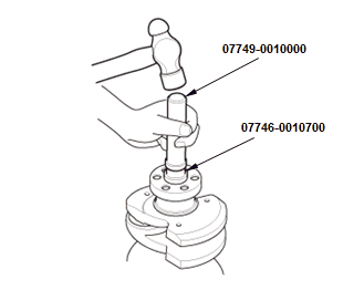
.png)
- Install the end bush when replacing the crankshaft. Using the driver handle, 15 x 135L and the bearing driver attachment, 24 x 26 mm, to drive the end bush squarely into the crankshaft to the specified installed height.
2. Crankshaft Main Bearing Clearance - Inspect
3. CKP Pulse Plate - Install
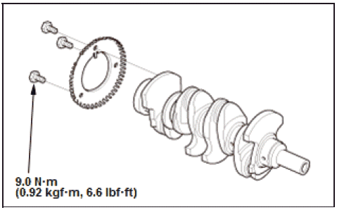
NOTE:
- Be careful not to damage the CKP pulse plate.
- Apply new engine oil to the threads of the CKP pulse plate mounting bolts.
4. Crankshaft - install
.png)
- Install the bearing halves in the engine block and the connecting rods
- Apply a coat of new engine oil to the main bearings and the connecting rod bearings
- Hold the crankshaft so rod journal No. 2 and rod journal No. 3 are straight up, then lower the crankshaft into the engine block.
NOTE : Be careful not to damage the journals and the CKP pulse plate.
5. Thrust Washer - Install
.png)
- Apply new engine oil to the thrust washer surfaces. Install the thrust washers in the No. 4 journal of the engine block.
6. Lower Block - Install
- Apply liquid gasket to the engine block mating surface of the lower block, and to the inside edge of the threaded bolt holes.
- Put the lower block on the engine block.
- Apply new engine oil to the threads and flange of the bearing cap bolts.
.png)
Fig. 8: Main Cap Tightening Sequence With Torque Specifications
- Tighten the bolts in three steps; tighten the bolts until the bolts sit
on the lower block, tighten the bolts
until the liquid gasket is compressed, tighten the bolts to specified
torque.
NOTE: Apply new engine oil to the threads and flange of the bearing cap bolts.
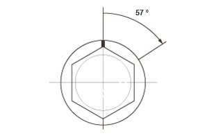
- Tighten the bearing cap bolts an additional 57º in the number sequence shown.
.png)
Fig. 9: Lower Block Tightening Sequence With Torque Specifications
- Tighten the 8mm bolts in three steps; tighten the bolts until the bolts sit on the lower block, tighten the bolts until the liquid gasket is compressed, tighten the bolts to specified torque.
7. Connecting Rod Bearing Clearance - Inspect
8. Connecting Rod Bolt - Inspect
.png)
- Measure the diameter of each connecting rod bolt at point A and point B
- Calculate the difference in diameter between point A and point B.
Point A - Point B = Difference in Diameter
Difference in Diameter
Specification: 0-0.05 mm (0-0.0020 in)
- If the difference in diameter is out of specification, replace the connecting rod bolt.
9. Connecting Rod Cap - Install
.png)
- Line up the mark (A) on the connecting rod and the connecting rod cap, then seat the rod journals into connecting rod No. 1 and connecting rod No. 4
- Apply new engine oil to the bolt threads and flanges, then install the bolts finger-tight
- Rotate the crankshaft clockwise
- Line up the mark on the connecting rod and the connecting rod cap, then seat the rod journals into connecting rod No. 2 and connecting rod No. 3
- Apply new engine oil to the bolt threads and flanges, then install the bolts finger-tight
- Torque the connecting rod bolts to 20 N.m (2.0 kgf.m, 15 lbf.ft).
- Tighten the connecting rod bolts an additional 90º.
NOTE: Remove the connecting rod bolt if you tightened it beyond the specified angle, do the connecting rod bolt inspection procedure. Do not loosen it back to the specified angle.
10. Engine Oil Strainer and Baffle Plate - Install
.png)
11. Oil Pan - Install
12. Transmission End Crankshaft Oil Seal - Install - Refer to: Pulley End Crankshaft Oil Seal Replacement - In Car, or Transmission End Crankshaft Oil Seal Replacement - In Car
13. Cylinder Head - Install
14. Transmission - Install
1. Install the transmission:
- M/T
- CVT
15. Pressure Plate, Clutch Disc, and Flywheel - Install (M/T)
16. Drive Plate - Install (CVT)
17. Engine/Transmission - Install
NOTE: The CKP pattern learn is required after this procedure.
READ NEXT:
 Drive Plate Removal and Installation (CVT)
Removal & Installation
1. Transmission Assembly - Remove
2. Drive Plate Assembly - Remove
Fig. 10: Drive Plate Bolt With Torque Specifications
Remove the drive plate (A) with the washer (B).
3
EVAP Canister Filter Removal and Installation(2WD)
Removal & Installation
1. EVAP Canister Filter - Remove
USA and Canada models
Disconnect the hoses (A).
Remove the EVAP canister filter
(B).
Mexico models
2. All Removed Parts - Install
I
Engine Assembly Torque Rod Removal and Installation
Removal & Installation
1. Engine Undercover - Remove (With Engine Undercover)
2. Engine - Support
Lift and support the engine with a transmission jack and a wood block
under the oil pan.
3. T
SEE MORE:
Accessory Power Sockets Electronic Wiring Diagram
Refer to appropriate wiring diagram. System Wiring Diagrams
GROUND CABLE ELECTRONIC WIRING DIAGRAM
Refer to appropriate wiring diagram. System Wiring Diagrams
PARASITIC DRAW CHECK
Special Tools Required
LH41 AC/DC low current clamp meter, FLULH41A**: Available through the Acura
Tool and Equipment
P
Clutch Pedal Position Switch A Test (M/T)
Test
1. Connector (Clutch Pedal Position Switch A) - Disconnect
Disconnect the connector (A).
2. Clutch Pedal Position Switch A - Test
Check for continuity between the terminals according to the table. If
the continuity is not as specified, replace clutch pedal position switch A.
3. All Re
