Honda HR-V: DTC Troubleshooting B2840-13, B2841-13: SRS Unit Connector Not Properly Installed
Honda HR-V (2015-2021) Service Manual / Restraints / Supplemental Restraint System - Diagnostics / DTC Troubleshooting / DTC Troubleshooting B2840-13, B2841-13: SRS Unit Connector Not
Properly Installed
NOTE:
- Before doing this troubleshooting procedure, find out if the vehicle was in a collision. If so, verify that all the required components were replaced with new components of the correct part number, and that they were properly installed.
- Before doing this troubleshooting procedure, review SRS Precautions and Procedures, General Troubleshooting Information, and 12 Volt Battery Terminal Disconnection and Reconnection.

1. Problem verification:
- Clear the DTCs with the HDS.
- Turn the vehicle to the ON mode, then wait for 10 seconds.
- Check for DTCs with the HDS.
1. Problem verification:
- Clear the DTCs with the HDS.
- Turn the vehicle to the ON mode, then wait for 10 seconds.
- Check for DTCs with the HDS.
2. Connector connection check:
- Turn the vehicle to the OFF (LOCK) mode.
- Check the following connector connections.
SRS unit connector A (39P)
SRS unit connector B (39P)
Are the connectors OK?
YES
Go to step 4.
NO
Go to step 3.
3. System check:
- Repair the poor connector connections whichever was the cause of the problem in step 2.
- Clear the DTCs with the HDS.
- Turn the vehicle to the ON mode, then wait for 10 seconds.
- Check for DTCs with the HDS.
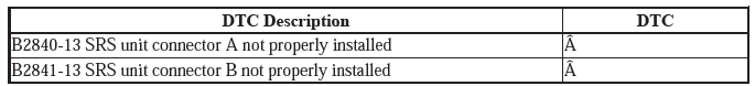
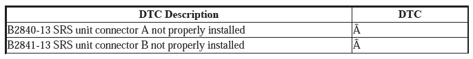
Are DTC B2840-13 and B2841-13 indicated?
YES
Turn the vehicle to the OFF (LOCK) mode, then go to step 4.
NO
The system is OK at this time.
4. SRS unit check:
- Disconnect the negative cable from the 12 volt battery, then wait at least 3 minutes.
- Disconnect the following connectors.
SRS unit connector A (39P)
SRS unit connector B (39P)
- Check for bent or damaged terminals on the SRS unit.
Are any terminals bent or damaged?
YES
Replace the SRS unit.
NO
Replace the dashboard wire harness or the floor wire harness, then clear the DTC.
READ NEXT:
 DTC Troubleshooting U0101-00: Lost Communication with the PCM (SRS
Unit)
DTC Troubleshooting U0101-00: Lost Communication with the PCM (SRS
Unit)
NOTE:
Before doing this troubleshooting procedure, find out if the vehicle was
in a collision. If so, verify
that all the required components were replaced with new components of the
correct pa
DTC Troubleshooting U0155-00: Lost Communication with the Gauge
Control
MODULE (SRS Unit)
NOTE:
Before doing this troubleshooting procedure, find out if the vehicle was
in a collision. If so, verify
that all the required components were replaced with new components of the
correct pa
Advanced Diagnostics
DTC ADVANCED DIAGNOSTICS: SRS RELATED DTCS
NOTE
Always check "How to troubleshoot the SRS system" and proceed along each
"DTC Troubleshooting"
procedure.
Make sure the 12 volt battery is fully c
SEE MORE:
DTC B0020-12
Special Tools Required
SRS Inflator Simulator 07SAZ-TB4011A
SRS Simulator Lead L 070AZ-SNAA300
NOTE:
Before doing this troubleshooting procedure, find out if the vehicle was
in a collision. If so, verify
that all the required components were replaced with new components of the
correct par
Keyless/Power Door Locks/Security System Symptom Troubleshooting - Auto Door
Unlock Does Not Work
NOTE:
Before testing, check the No. C1 (20 A), No. C4 (10 A), No. C5 (10 A),
No. C6 (10 A), No. C7 (10 A),
No. C12 (10 A), and No. C13 (10 A) fuses in the under-dash fuse/relay box
are OK.
There are two pairs of fuses in the same circuit (No. C6 and No. C7
fuses, No. C5 and No. C13 fuses,
© 2019-2026 Copyright www.hohrv2.com
