Honda HR-V: DTC Troubleshooting U0101-00: Lost Communication with the PCM (SRS Unit)
NOTE:
- Before doing this troubleshooting procedure, find out if the vehicle was in a collision. If so, verify that all the required components were replaced with new components of the correct part number, and that they were properly installed.
- Before doing this troubleshooting procedure, review SRS Precautions and Procedures, General Troubleshooting Information, and 12 Volt Battery Terminal Disconnection and Reconnection.
- Before replacing the SRS unit, check the SRS unit software version with the HDS. If the software version is not the latest, update the SRS unit software, and retest.

1. Body electrical system check:
Check for any F-CAN and B-CAN communication DTCs with the HDS.

Are there any communication DTCs?
YES
Go to the appropriate DTC troubleshooting.
NO
Go to step 2.
2. DTC check:
- Clear the DTCs with the HDS.
- Turn the vehicle to the ON mode, then wait for 10 seconds.
- Check for DTCs with the HDS.

Is DTC U0101-00 indicated?
YES
Go to step 3.
NO
Intermittent failure, the system is OK at this time. Go to Troubleshooting Intermittent Failures. If another DTC is indicated, troubleshoot the DTC.
3. PGM-FI system check:
- Turn the vehicle to the OFF (LOCK) mode.
- Start the engine, and see if the malfunction indicator lamp (MIL) also stays on.
Does the MIL stay on longer than 30 seconds?
YES
Go to the Fuel and Emissions Systems General Troubleshooting Information - Refer to: How to Troubleshoot the Fuel and Emissions Systems, or How to Troubleshoot the CVT System (CVT).
NO
Go to step 4.
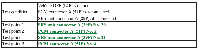
4. Open wire check (F-CAN_H, F-CAN_L lines):
- Turn the vehicle to the OFF (LOCK) mode.
- Jump the SCS line with the HDS, and wait more than 1 minute.
NOTE: This step must be done to protect the PCM from damage.
- Disconnect the following connector.
PCM connector A (51P)
- Disconnect the negative cable from the 12 volt battery, then wait at least 3 minutes.
- Disconnect the following connector.
SRS unit connector A (39P)
- Check for continuity between test points 1 and 2.
Is there continuity?
YES
The F-CAN_H and F-CAN_L wires are OK. Faulty SRS unit or poor connection at SRS unit connector A (39P) and the SRS unit. Check the connection; if the connection is OK, replace the SRS unit. If the DTC does not clear, replace the left engine compartment wire harness or the dashboard wire harness.
NO
Open in the harness between SRS unit connector A (39P) terminal No. 20 and PCM connector A (51P) terminal No. 3, or between SRS unit connector A (39P) terminal No. 21 and PCM connector A (51P) terminal No. 4 (left engine compartment wire harness or dashboard wire harness); replace the faulty harness, then clear the DTC.
READ NEXT:
 DTC Troubleshooting U0155-00: Lost Communication with the Gauge
Control
MODULE (SRS Unit)
DTC Troubleshooting U0155-00: Lost Communication with the Gauge
Control
MODULE (SRS Unit)
NOTE:
Before doing this troubleshooting procedure, find out if the vehicle was
in a collision. If so, verify
that all the required components were replaced with new components of the
correct pa
Advanced Diagnostics
DTC ADVANCED DIAGNOSTICS: SRS RELATED DTCS
NOTE
Always check "How to troubleshoot the SRS system" and proceed along each
"DTC Troubleshooting"
procedure.
Make sure the 12 volt battery is fully c
SEE MORE:
DTC 1101 Media Bus Send Error
NOTE:
Check the vehicle 12 volt battery condition first.
This audio DTC sets when there is an internal error in BUS sending.
Before you troubleshoot, make sure to follow the General Troubleshooting
Information.
1. Problem verification:
Clear the hard error codes.
Turn the vehicle to the OF
DTC Troubleshooting 31-11, 32-11, 33-11, 34-11, 35-11, 36-11, 37-11,
38-11: ABS Solenoid Valve Malfunction
NOTE: Before you troubleshoot, review the general troubleshooting
information.
1. Problem verification:
Turn the vehicle to the ON mode.
Clear the DTC with the HDS.
Turn the vehicle to the OFF (LOCK) mode, then to the ON mode.
Check for DTCs with the HDS.
Is DTC 31-11, 32-11, 33-11, 34-11,
