Honda HR-V: DTC Troubleshooting U0155-00: Lost Communication with the Gauge Control MODULE (SRS Unit)
NOTE:
- Before doing this troubleshooting procedure, find out if the vehicle was in a collision. If so, verify that all the required components were replaced with new components of the correct part number, and that they were properly installed.
- Before doing this troubleshooting procedure, review SRS Precautions and Procedures, General Troubleshooting Information, and 12 Volt Battery Terminal Disconnection and Reconnection.
- Before replacing the SRS unit, check the SRS unit software version with the HDS. If the software version is not the latest, update the SRS unit software, and retest.

1. Body electrical system check:
Check for any F-CAN and B-CAN communication DTCs with the HDS.

Are there any communication DTCs?
YES
Go to the appropriate DTC troubleshooting.
NO
Go to step 2.
2. Brake system indicator check:
Release the parking brake, turn the vehicle to the ON mode, and see if the brake system indicator comes on for 2 seconds and then goes off.
Does the brake system indicator come on and then go off after 2 second?
YES
Go to step 3.
NO
Do the gauge control module self-diagnostic function. If gauge control module has the problem, replace the gauge control module, then clear the DTC, and retest. If the DTC is still present, replace the SRS unit.
3. DTC check:
- Clear the DTCs with the HDS.
- Turn the vehicle to the ON mode, then wait for 10 seconds.
- Check for DTCs with the HDS.

Is DTC U0155-00 indicated?
YES
Go to step 4.
NO
Intermittent failure, the system is OK at this time. Go to Troubleshooting Intermittent Failures. If another DTC is indicated, troubleshoot the DTC.
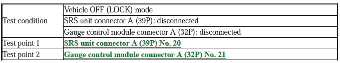
4. Open wire check (F-CAN_H, F-CAN_L lines):
- Turn the vehicle to the OFF (LOCK) mode.
- Disconnect the negative cable from the 12 volt battery, then wait at least 3 minutes.
- Disconnect the following connectors.
SRS unit connector A (39P)
Gauge control module connector A (32P)
- Check for continuity between test points 1 and 2.

Is there continuity?
YES
The F-CAN_H and F-CAN_L wires are OK. Faulty SRS unit or poor connection at SRS unit connector A (39P) and the SRS unit. Check the connection; if the connection is OK, replace the SRS unit. If the DTC does not clear, replace the dashboard wire harness.
NO
Open in the harness between SRS unit connector A (39P) terminal No. 20 and gauge control module connector A (32P) terminal No. 21, or between SRS unit connector A (39P) terminal No. 21 and gauge control module connector A (32P) terminal No. 22; replace the dashboard wire harness, then clear the DTC.
DTC TROUBLESHOOTING U3000-51: SRS UNIT PROGRAMMING ERROR (SRS UNIT)
NOTE:
- Before doing this troubleshooting procedure, find out if the vehicle was in a collision. If so, verify that all the required components were replaced with new components of the correct part number, and that they were properly installed.
- This DTC is indicated when the SRS unit update is not completed properly.
- Never press the engine start/stop button, while updating the SRS unit. If you press the engine start/stop button, before you complete the SRS unit update procedure, the SRS unit can be damaged. If there is a problem with the update, keep the vehicle in ON mode.
- Before doing this troubleshooting procedure, review SRS Precautions and Procedures and General Troubleshooting Information.

1. Problem verification (update):
- Do the SRS unit update procedure.
- Clear the DTCs with the HDS.
- Turn the vehicle to the ON mode, then wait for 10 seconds.
- Check for DTCs with the HDS.

Is DTC U3000-51 indicated?
YES
The failure is duplicated. Replace the SRS unit.
NO
Update is complete.
READ NEXT:
 Advanced Diagnostics
DTC ADVANCED DIAGNOSTICS: SRS RELATED DTCS
NOTE
Always check "How to troubleshoot the SRS system" and proceed along each
"DTC Troubleshooting"
procedure.
Make sure the 12 volt battery is fully c
Battery Management System - Service Information
REMOVAL & INSTALLATION
12 VOLT BATTERY SENSOR REMOVAL AND INSTALLATION
Removal
1. 12 Volt Battery Sensor - Remove
Make sure the vehicle to the OFF (LOCK) mode.
Disconnect the connector (A).
R
SEE MORE:
Select Arm Clearance Inspection (M/T)
Inspection
1. Select Arm Clearance - Inspect
Measure the clearance between the select arm (A) and the interlock (B)
with a
feeler gauge (C). If the clearance exceeds the service limit, go to step 2.
Standard: 0.01-0.21 mm (0.0004-0.0083 in)
Service Limit: 0.21 mm (0.0083 in)
Measure the wi
About Your Seat Belts
Seat belts are the single most effective safety device because they keep you
connected to the vehicle so that you can take advantage of many built-in safety
features. They also help keep you from being thrown against the inside of the
vehicle, against other passengers, or out of the vehicle. When wo
