Honda HR-V: Engine Oil Pump Removal and Installation
Removal
1. Right Front Wheel - Remove
2. Front Splash Shield and Engine Undercover (With Engine Undercover) - Remove
3. Drive Belt Auto-Tensioner - Remove
4. Drive Belt Idler Pulley Base - Remove
5. Crankshaft Pulley - Remove
6. Cylinder Head Cover - Remove
7. PCV Hose (Oil Pump Side) - Disconnect
8. Side Engine Mount - Remove
NOTE: Do not remove the bolt that tighten the side engine mount and the side engine mount bracket.
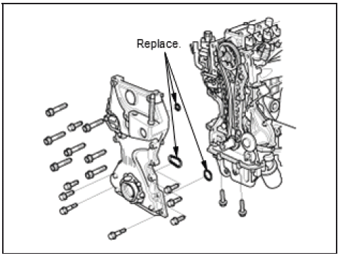
9. Engine Oil Pump - Remove
Installation
1. Engine Oil Pump - Install
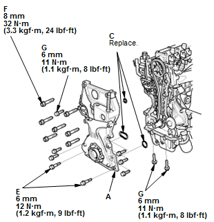
Fig. 21: Engine Oil Pump Exploded View With Torque Specifications
.png)
- Check the pulley end crankshaft oil seal for damage. If the oil seal is damaged, replace the pulley end crankshaft oil seal - Refer to: Pulley End Crankshaft Oil Seal Replacement - In Car, or Transmission End Crankshaft Oil Seal Replacement - In Car.
- Apply liquid gasket to the engine block and the oil pan mating surface of the oil pump, and to the inside edge of the threaded bolt holes.
- Set the edge of the oil pump (A) on the edge of the oil pan (B) with new O-rings (C).
- Install the oil pump on the engine block (D).
NOTE: When installing the oil pump, do not slide the bottom surface onto the oil pan mounting surface. - Loosely install the dowel bolts (E), then tighten the 8 mm bolts (F), the 6 mm bolts (G), and the dowel bolts.
- Wipe off the excess liquid gasket on the oil pan and the oil pump mating surface.
- Clean the excess oil off the crankshaft, and check that the pulley end crankshaft oil seal lip is not distorted.
2. Side Engine Mount - Install
3. PCV Hose (Oil Pump Side) - Connect
4. Cylinder Head Cover - Install
5. Crankshaft Pulley - Install
6. Drive Belt Idler Pulley Base - Install
7. Drive Belt Auto-Tensioner - Install
8. Front Splash Shield and Engine Undercover (With Engine Undercover) - Install
9. Right Front Wheel - Install
READ NEXT:
 Engine Removal and Installation
Special Tools Required
Universal Lifting
Eyelet 07AAKSNAA120
Removal
NOTE:
Use fender covers to avoid damaging painted surfaces.
To avoid damaging the wiring and terminals, unplug the wiring conne
FTP Sensor Removal and Installation (KA/KC)
Removal & Installation
1. EVAP Canister Assembly - Remove - Refer to: EVAP Canister Removal and
Installation (AWD), or
EVAP Canister Removal and Installation (KA/KC)
2. FTP Senor - Remove
Disc
Injector Removal and Installation
Removal
1. Fuel Pressure - Relieve
2. Fuel Injector and Rail Assembly - Remove
Disconnect the injector connectors (A).
Remove the harness clamp (B).
Disconnect the quick-connect fitting (C).
Rem
SEE MORE:
Poor AM Or FM Radio Reception Or Interference (Without Navigation)
NOTE:
Check the vehicle 12 volt battery condition first.
Check for aftermarket accessories plugged into the vehicle accessory
power sockets.
Check the radio reception in an open area. Compare it to a known-good
vehicle whenever possible. Poor reception/interference can be caused by the
fol
Fuel Fill Pipe Removal and Installation (KA/KC)
Removal and Installation
1. Fuel Pressure - Relieve
2. Fuel Tank - Drain
3. Fuel Cap Adapter - Remove
4. Front Floor Undercover - Remove - Refer to: Rear Floor Undercover Removal
and Installation
(2WD), or Front Floor Undercover Removal and Installation (2WD)
5. Performance Rod - Remove
6. Filler N
