Honda HR-V: FTP Sensor Removal and Installation (KA/KC)
Honda HR-V (2015-2021) Service Manual / Engine / Engine Control System & Engine Mechanical - Service Information / FTP Sensor Removal and Installation (KA/KC)
Removal & Installation
1. EVAP Canister Assembly - Remove - Refer to: EVAP Canister Removal and Installation (AWD), or EVAP Canister Removal and Installation (KA/KC)
2. FTP Senor - Remove
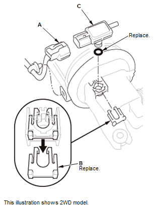
- Disconnect the connector (A).
- Remove the retainer (B), then remove the FTP sensor (C).
3. All Removed Parts - Install
- Install the parts in the reverse order of removal with a new O-ring and a new retainer.
IMT ACTUATOR REMOVAL AND INSTALLATION
Removal & Installation
1. Intake Manifold - Remove
2. IMT Actuator - Remove
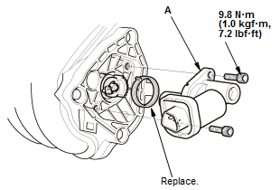
- Remove the IMT actuator (A).
3. All Removed Parts - Install
- Install the parts in the reverse order of removal with a new O-ring.
IMT VALVE REMOVAL AND INSTALLATION
Removal & Installation
1. IMT Actuator - Remove
2. IMT Valve - Remove
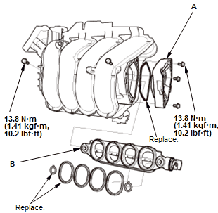
Fig. 24: IMT Valve Exploded View With Torque Specifications
- Remove the IMT cover (A)
- Remove the IMT valve (B).
3. All Removed Parts - Install
- Install the parts in the reverse order of removal with a new O-rings.
READ NEXT:
 Injector Removal and Installation
Removal
1. Fuel Pressure - Relieve
2. Fuel Injector and Rail Assembly - Remove
Disconnect the injector connectors (A).
Remove the harness clamp (B).
Disconnect the quick-connect fitting (C).
Rem
Intake Air Resonator Removal and Installation
Removal & Installation
1. Air Intake Duct - Remove
2. Intake Air Resonator Mounting Bolt - Remove
3. Left Front Splash Shield - Remove
4. Left Front Inner Fender - Remove - Refer to: Front Inner
Knock Sensor Removal and Installation
Removal & Installation
1. Intake Manifold - Remove
2. Knock Sensor - Remove
Fig. 28: Knock Sensor Location With Torque Specifications
Disconnect the connector (A)
Remove the knock sensor (B).
SEE MORE:
Fuel Tank Unit Disassembly and Reassembly (AWD)
Disassembly/Reassembly
The fuel filter should be replaced whenever the fuel pressure drops below the
specified value, after making sure
that the fuel pump and the fuel pressure regulator are OK.
Fuel Pump/Fuel Gauge Sending Unit
1. Fuel Tank Unit - Remove - Refer to: Fuel Tank Unit Removal and
Ins
Using HFL
■HFL Buttons
(Pick-up) button: Press to go
directly to the Phone screen, or to answer an
incoming call.
(Hang-up/Back) button: Press
to end a call, go back to the previous
command, or to cancel a command.
(Talk) button: Press to call a
number with a stored voice tag, a phonebook,
name, or a
© 2019-2026 Copyright www.hohrv2.com
