Honda HR-V: Engine Removal and Installation
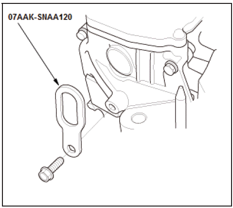
Special Tools Required
Universal Lifting Eyelet 07AAKSNAA120
Removal
NOTE:
- Use fender covers to avoid damaging painted surfaces.
- To avoid damaging the wiring and terminals, unplug the wiring connectors carefully while holding the connector portion.
- Mark all wiring and hoses to avoid misconnection. Also, be sure that they do not contact other wiring or hoses, or interfere with other parts.
1. Hood - Wide Open
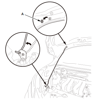
- Open the hood, and remove the plug cap (A).
- Change the hood support rod mounting position.
- Secure it with the hood support rod in the wide-open position.
2. Fuel Pressure - Relieve
NOTE: After relieving the fuel pressure, do not connect the quick-connect fitting.
3. 12 Volt Battery Terminal - Disconnect
4. Positive Cable (12 Volt Battery Terminal Fuse Box) - Disconnect
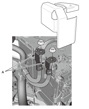
- Remove the cover.
- Disconnect the positive cables (A).
5. 12 Volt Battery - Remove
6. Front Grille Cover - Remove
7. Air Cleaner - Remove
8. Intake Air Duct - Remove
9. Intake Air Resonator - Remove
10. EVAP Canister Purge Hose and Brake Booster Vacuum Hose - Disconnect
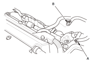
- Disconnect the EVAP canister purge hose (A) and the brake booster vacuum hose (B).
11. Connector (PCM) - Disconnect
12. Connector (Engine Wire Harness) - Disconnect

- Disconnect the connectors (A)
- Remove the harness holder clamp (B) and the harness clamps (C).
13. Change Wire Bracket - Remove (M/T)
14. Slave Cylinder - Move (M/T)
NOTE: Without disconnecting the clutch line.
15. Shift Cable (Transmission Side) - Disconnect (CVT)
16. Steering Joint - Disconnect
NOTE: Hold the steering wheel in the steering wheel holder tool.
17. Vehicle - Lift
- Raise and support the vehicle.
18. Front Wheel - Remove
19. Front Splash Shield and Engine Undercover (With Engine Undercover) - Remove
20. Drive Belt - Remove
21. A/C Pipe Clamp Bolt - Remove
22. Engine Coolant - Drain
23. Radiator - Remove
24. Engine Oil - Drain
25. Transmission Fluid - Drain
- Drain the transmission fluid:
- M/T
- CVT
26. Exhaust Pipe A - Remove
27. Front Stabilizer Link Ball Joint - Disconnect
28. Lower Arm Ball Joint - Disconnect
29. Tie-Rod End Ball Joint - Disconnect
30. Front Driveshaft - Remove
31. Propeller Shaft - Remove (AWD)
32. A/C Compressor - Move
NOTE:
- Do not disconnect the A/C hoses.
- Do not bend the A/C hoses excessively.
- Disconnect the connector at the same time.
- Hang the A/C compressor with a wire tie.
33. Torque Rod - Remove
34. Front Subframe - Support
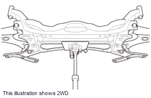
- Support the front subframe with a transmission jack.
35. Front Subframe - Remove
36. Vehicle - Lift
- Lower the vehicle.
37.Heater Hose - Disconnect
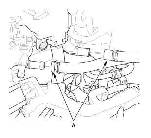
- Disconnect the heater hoses (A).
38. Engine - Support
- Lift and support the engine with a jack and a wood block under the oil pan.
39. Side Engine Mount - Remove
NOTE: Do not remove the bolt that tighten the side engine mount and the side engine mount bracket.
40. Universal Lifting Eyelet - Install
41. Chain Hoist - Install
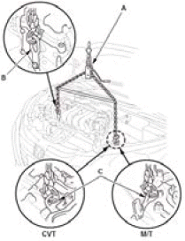
- Attach the chain hoist (A) to the universal lifting eyelet (B) and the transmission hanger (C), then lift the engine/transmission until it is securely supported by the chain hoist.
42. Transmission Mount Bracket Mounting Bolt and Nut - Remove
43. Engine - Remove
- Check that the engine/transmission is completely free of the vacuum hoses, the fuel hoses, the coolant hoses, and the electrical wiring.
- Slowly lower the engine/transmission about 150 mm (5.91 in). Check once again that all the hoses and the electrical wiring are disconnected and free from the engine/transmission, then lower it all the way and support it.
- Remove the chain hoist from the engine/transmission.
- Raise the vehicle, and remove the engine/transmission from under the vehicle.
Installation
1. Accessory Bracket - Install
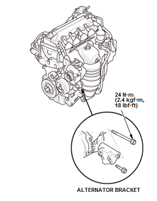
Fig. 22: Alternator Bracket Location With Torque Specifications
- If the alternator bracket is removed, install the alternator bracket.
- If the A/C compressor bracket is removed, install the A/C compressor bracket.
- If the torque rod bracket is removed, install the torque rod bracket.
NOTE: Always use new bolts.
(2WD)
2. Universal Lifting Eyelet - Install

3. Engine - Install
- Attach the chain hoist (A) to the universal lifting eyelet (B) and the transmission hanger (C), then lift the engine/transmission until it is securely supported by the chain hoist.
- Position the engine/transmission under the vehicle. Be sure that they
are properly aligned.
Carefully lower the vehicle until the engine/transmission are properly positioned in the engine compartment. Make sure the vehicle is not resting on any part of the engine/transmission.
Support the engine/transmission with the chain hoist and carefully raise the engine/transmission into place.
4. Transmission Mount Bracket Mounting Bolt and Nut - Loosely Install
NOTE: Always use new bolts and new nuts.
5. Engine - Support
- Lift and support the engine with a jack and a wood block under the oil pan.
6. Chain Hoist and Universal Lifting Eyelet - Remove
7. Side Engine Mount - Loosely Install
NOTE:
- Always use new bolts and new nuts.
- Connect the ground cable at the same time.
8. Vehicle - Lift
- Raise the vehicle.
9. Front Subframe - Support

- Support the front subframe with a transmission jack.
10.Front Subframe - Install
11.Torque Rod - Loosely Install
NOTE: Always use new bolts.
12.Vehicle - Lift
- Lower the vehicle.
13.All Engine Mount Mounting Bolt and Nut - Tighten
14.Vehicle - Lift
- Raise the vehicle.
15.A/C Compressor - Install
NOTE: Connect the connector at the same time.
16.Propeller Shaft - Install (AWD)
17.Front Driveshaft - Install
18.Tie-Rod End Ball Joint - Connect
19.Lower Arm Ball Joint - Connect
20.Front Stabilizer Link Ball Joint - Connect
21.Exhaust Pipe A - Install
22.Drive Belt - Install
23.A/C Pipe Clamp Bolt - Install
24.Radiator - Install
25.Front Splash Shield and Engine Undercover (With Engine Undercover) - Install
26.Front Wheel - Install
27.Vehicle - Lift
- Lower the vehicle.
28.Steering Joint - Connect
29.Heater Hose - Connect

- Connect the heater hoses (A).
30.Slave Cylinder - Install (M/T)
31.Change Wire Bracket - Install (M/T)
32.Shift Cable (Transmission Side) - Connect (CVT)
33.Fuel Feed Hose (Fuel Rail Side) - Connect
34.Connector (Engine Wire Harness) - Connect
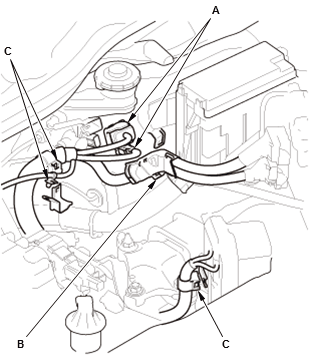
- Connect the connectors (A)
- Install the harness holder clamp (B) and the harness clamps (C).
35.Connector (PCM) - Connect
36.EVAP Canister Purge Hose and Brake Booster Vacuum Hose - Connect
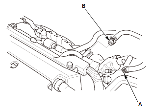
- Connect the EVAP canister purge hose (A) and the brake booster vacuum hose (B).
37.Intake Air Resonator - Install
38.Intake Air Duct - Install
39.Air Cleaner and Air Intake Duct - Install
40.Front Grille Cover - Install
41.12 Volt Battery - Install
NOTE: Do not connect the 12 Volt battery negative terminal in this step.
42.Positive Cable (12 Volt Battery Terminal Fuse Box) - Connect
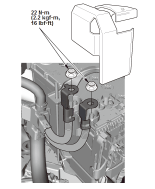
Fig. 23: Battery Cables At Terminal Fuse Box With Torque Specifications
- Connect the positive cables
- Install the cover.
43.12 Volt Battery Terminal - Connect
44.Fuel Leak - Inspect
- Turn the vehicle to the ON mode, but do not operate the starter. After the fuel pump runs for about 2 seconds, the fuel rail will be pressurized. Repeat this two or three times, then check for fuel leakage.
45.Engine Oil - Refill
46.Transmission Fluid - Refill
- Refill the transmission fluid:
- M/T
- CVT
47.Engine Coolant - Refill/Air Bleed
48.Transmission Gear - Check
- M/T: Check that the transmission shifts into all gears smoothly
- CVT: Move the shift lever to each gear, and verify that the A/T gear position indicator follows the transmission range switch.
49.PCM - Reset
50.CKP Pattern - Clear/Learn
51.Idle Speed - Inspect
52.Ignitiion Timing - Inspect
53.Wheel Alignment - Check
54.VSA Sensor Neutral Position - Memorization
READ NEXT:
 FTP Sensor Removal and Installation (KA/KC)
Removal & Installation
1. EVAP Canister Assembly - Remove - Refer to: EVAP Canister Removal and
Installation (AWD), or
EVAP Canister Removal and Installation (KA/KC)
2. FTP Senor - Remove
Disc
Injector Removal and Installation
Removal
1. Fuel Pressure - Relieve
2. Fuel Injector and Rail Assembly - Remove
Disconnect the injector connectors (A).
Remove the harness clamp (B).
Disconnect the quick-connect fitting (C).
Rem
Intake Air Resonator Removal and Installation
Removal & Installation
1. Air Intake Duct - Remove
2. Intake Air Resonator Mounting Bolt - Remove
3. Left Front Splash Shield - Remove
4. Left Front Inner Fender - Remove - Refer to: Front Inner
SEE MORE:
Tire Pressure Monitoring System (TPMS)
U.S. models only
Instead of directly measuring the pressure in each tire, the TPMS on this
vehicle
monitors and compares the rolling radius and rotational characteristics of each
wheel and tire while you are driving to determine if one or more tires are
significantly under-inflated. This will cause
Horn Removal, Installation, and Test
Removal & Installation
1. Front Bumper - Remove
2. Horn - Remove
Fig. 2: (High) Horn Bracket Torque Specifications
Fig. 3: (Low) Horn Bracket Torque Specifications
Horn (High)
Disconnect the connector (A)
Horn (Low)
Remove the horn (B).
3. All Removed Parts - Install
Install the parts
