Honda HR-V: Intake Air Resonator Removal and Installation
Removal & Installation
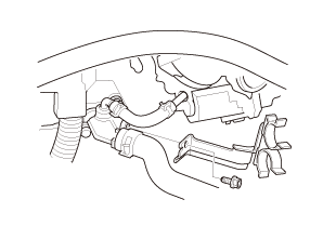
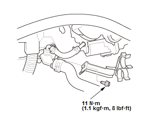
1. Air Intake Duct - Remove
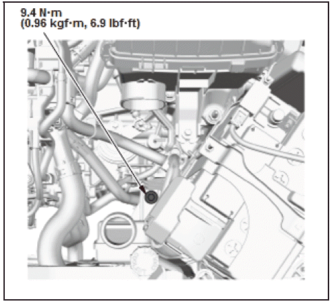
2. Intake Air Resonator Mounting Bolt - Remove
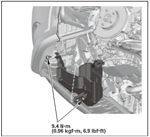
3. Left Front Splash Shield - Remove
4. Left Front Inner Fender - Remove - Refer to: Front Inner Fender Removal and Installation, or Rear Inner Fender Removal and Installation
NOTE: Remove an appropriate portion of the left front inner fender.
5. Intake Air Resonator - Remove
6. All Removed Parts - Install
- Install the parts in the reverse order of removal.
INTAKE MANIFOLD REMOVAL AND INSTALLATION
Exploded View
1. Intake Manifold Exploded View
Exploded View
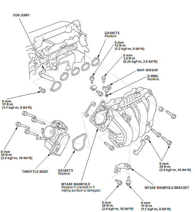
Fig. 25: Intake Manifold Exploded View With Torque Specifications
Removal
NOTE: Refer to the Exploded View if needed during this procedure.
1. Fuel Pressure - Relieve
NOTE: After relieving the fuel pressure, do not connect the quick-connect fitting.
2. 12 Volt Battery Terminal - Disconnect
3. Air Cleaner - Remove
4. Intake Air Duct - Remove
5. Connector (MAP Sensor) - Disconnect
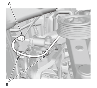
6. EVAP Canister Purge Hose, Brake Booster Vacuum Hose, and PCV Hose - Disconnect
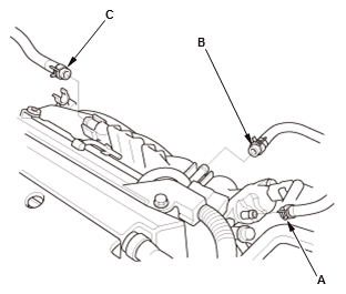
- Disconnect the EVAP canister purge hose (A), the brake booster vacuum hose (B), and the PCV hose (C).
7. Throttle Body - Move
NOTE: Do not disconnect the water bypass hoses.
8. Heater Hose Clamp Bracket - Remove
- Remove the heater hose clamp bracket.
9. Engine Undercover - Remove (With Engine Undercover)
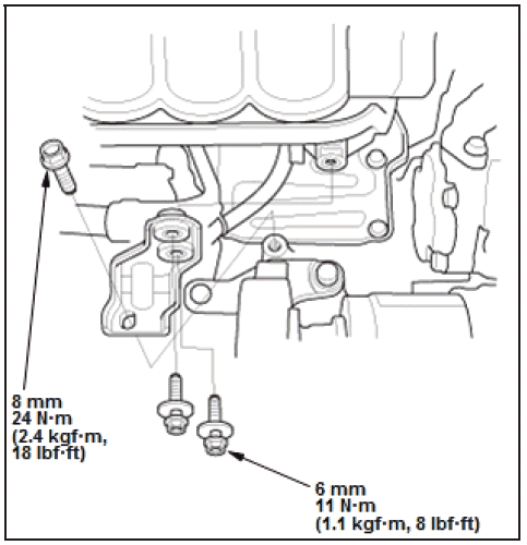
10.Intake Manifold Bracket - Remove
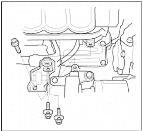
11.Connector (IMT Valve Actuator) - Disconnect

- Disconnect the connector (A)
- Remove the harness clamps (B).
12.Intake Manifold - Remove
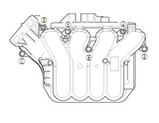
Fig. 26: Intake Manifold Removal Seqence
Installation
NOTE: Refer to the Exploded View if needed during this procedure.
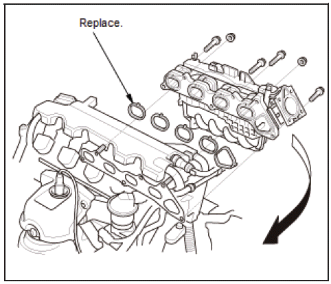
1. Intake Manifold - Install
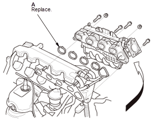
- Loosely install the intake manifold with new gaskets (A).
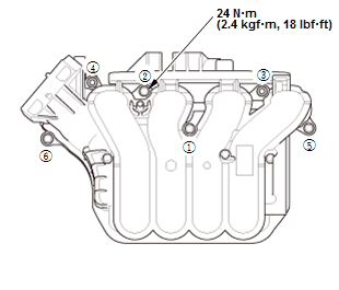
Fig. 27: Intake Manifold Tightening Sequence With Torque Specifications
- Tighten the bolts/nuts in three steps; tighten the bolts/nuts until the bolts/nuts sit on the intake manifold, tighten the bolts/nuts until the gasket is compressed, tighten the bolts/nuts to specified torque.
2. Connector (IMT Valve Actuator) - Connect
- Connect the connector (A)
- Install the harness clamps (B).
3. Intake Manifold Bracket - Install
4. Engine Undercover - Install (With Engine Undercover)
5. Heater Hose Clamp Bracket - Install
- Install the heater hose clamp bracket.
6. Install the heater hose clamp bracket.
NOTE: Always use a new throttle body gasket.
7. EVAP Canister Hose, Brake Booster Vacuum Hose, and PCV Hose - Connect

- Connect the EVAP canister purge hose (A), the brake booster vacuum hose (B), and the PCV hose (C).
8. Connector (MAP Sensor) - Connect
9. Air Cleaner - Install
10.Fuel Feed Hose (Fuel Rail Side) - Connect
11.12 Volt Battery Terminal - Connect
12.Fuel Leak - Inspect
- Turn the vehicle to the ON mode, but do not operate the starter. After the fuel pump runs for about 2 seconds, the fuel rail will be pressurized. Repeat this two or three times, then check for fuel leakage.
READ NEXT:
 Knock Sensor Removal and Installation
Removal & Installation
1. Intake Manifold - Remove
2. Knock Sensor - Remove
Fig. 28: Knock Sensor Location With Torque Specifications
Disconnect the connector (A)
Remove the knock sensor (B).
PCM Removal and Installation
Removal
NOTE:
Make sure the HDS or the MVCI has the latest HDS software version.
If you are replacing the PCM after substituting a known-good PCM,
reinstall the original PCM, then do
this proced
Piston, Ring, Pin, and Connecting Rod Removal and Installation
Removal
1. Crankshaft - Remove
2. Oil Jet - Remove
3. Metal or Hard Carbon - Remove
If you can feel a ridge of metal or hard carbon around the top of each
cylinder,
remove it with a ridge reamer
SEE MORE:
Keyless/Power Door Locks/Security System Symptom Troubleshooting - Security
Alarm System Will Not Arm
NOTE: Before troubleshooting, check the B-CAN DTCs. If any DTC is indicated,
troubleshoot the indicated
DTC first.
1. Switch information check:
Turn the vehicle to the ON mode.
Check the parameter(s) below with the HDS.
Is each switch information OK?
YES
Intermittent failure, the system is OK
DTC B0072-1A
Special Tools Required
SRS Short Canceller 070AZ-SAA0100
NOTE:
Before doing this troubleshooting procedure, find out if the vehicle was
in a collision. If so, verify
that all the required components were replaced with new components of the
correct part number,
and that they were properly ins
