Honda HR-V: Intermediate Shaft Disassembly and Reassembly
Honda HR-V (2015-2021) Service Manual / Driveline & Axles / Driveshafts - Overhaul, Inspection & Adjustment / Disassembly and Reassembly / Intermediate Shaft Disassembly and Reassembly
Special Tools Required
Half Shaft Base 07NAF-SR30101
Oil Seal Driver, 44.5 mm 07947-SB00100
Driver Handle, 15 x 135L 07749-0010000
Bearing Driver Attachment, 52 x 55 mm 07746-0010400
Oil Seal Driver, 65 mm 07JAD-PL90100
Bearing Driver Attachment, 35 mm I.D.
07746-0030400
Exploded View
1. Intermediate Shaft - Exploded View
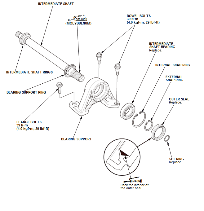
Fig. 2: Exploded View Of Intermediate Shaft
Disassembly
1. Intermediate Shaft - Remove
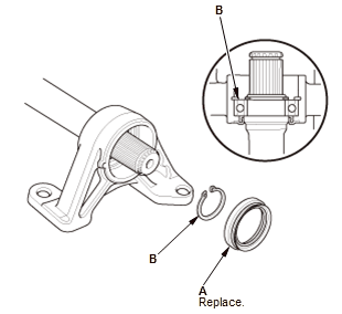
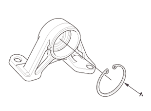
- Remove the outer seal (A)
- Remove the external snap ring (B).
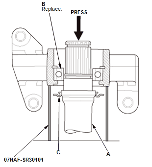
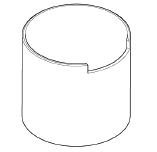
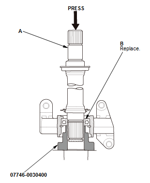
- Press the intermediate shaft (A) out of the intermediate shaft bearing
(B) using the half shaft base and a press.
NOTE: Be careful not to damage the bearing support ring (C) on the intermediate shaft during disassembly.
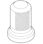
2. Intermediate Shaft Bearing - Remove
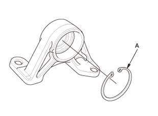
- Remove the internal snap ring (A).
- Press the intermediate shaft bearing (A) out of the bearing support (B) using the half shaft base, the 65 mm oil seal driver attachment, and a press.
Reassembly
Refer to the Exploded View as needed during this procedure.
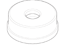
1. Intermediate Shaft Bearing - Install
- Clean the disassembled parts with solvent.
NOTE: Do not wash the rubber parts with solvent.
- Dry the disassembled parts with compressed air.
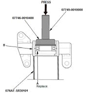
- Press a new intermediate shaft bearing (A) into the bearing support (B) using the 52 x 55 mm bearing driver attachment, the 15 x 135L driver handle, and a press.
- Install the internal snap ring (A).
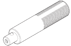
2. Intermediate Shaft - Install
- Press the intermediate shaft (A) into the shaft bearing (B) using a press.
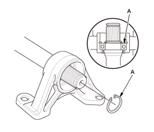
- Install the external snap ring (A).
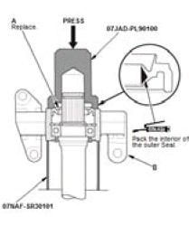
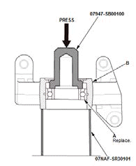
- Install a new outer seal (A) into the bearing support (B) using the 65 mm oil seal driver, the half shaft base, and a press. Press in the seal until it is even with the surface of the bearing support.
READ NEXT:
 Rear Driveshaft Disassembly and Reassembly (AWD)
Special Tools Required
Slide Hammer 5/8"-18 UNF, commercially available
Threaded Adapter, 22 x 1.5 mm 07XAC-001010A
Boot Band Clamp Tool Kent-Moore J-35910 or
equivalent, commercially available
CV
SEE MORE:
Starting System - Service Information
REMOVAL & INSTALLATION
ENGINE START/STOP SWITCH REMOVAL AND INSTALLATION
Removal and Installation
1. Dashboard switch Panel - Remove
2. Engine Start/Stop Switch - Remove
3. All Removed Parts - Install
Install the parts in the reverse order of removal.
STARTER REMOVAL, INSTALLATION, AND PERFO
DTC Troubleshooting 71-11, 71-12, 71-13, 71-14, 71-15, 71-16: Different
Diameter Tire Malfunction
NOTE:
The DTC will be indicated when the vehicle has a different diameter
tire(s) compared to the other tires.
Before you troubleshoot, review the general troubleshooting information.
1. Problem verification:
Check the tires for proper inflation and the correct size.
Turn the vehicle to t
© 2019-2026 Copyright www.hohrv2.com
