Honda HR-V: Rear Driveshaft Disassembly and Reassembly (AWD)
Special Tools Required
Slide Hammer 5/8"-18 UNF, commercially available
Threaded Adapter, 22 x 1.5 mm 07XAC-001010A
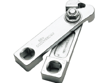
Boot Band Clamp Tool Kent-Moore J-35910 or equivalent, commercially available
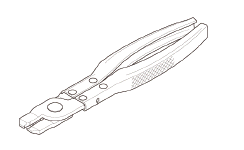
CV Boot Clamp Pliers 30500, commercially available
Exploded View
1. Driveshaft - Exploded View
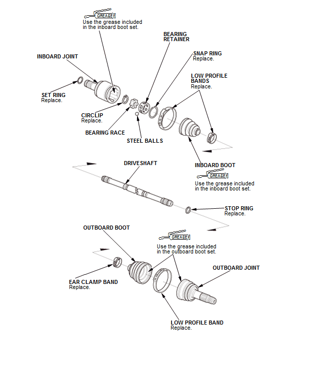
Fig. 3: Exploded View Of Driveshaft
Disassembly
NOTE: Be careful not to damage the boot.
Inboard Joint
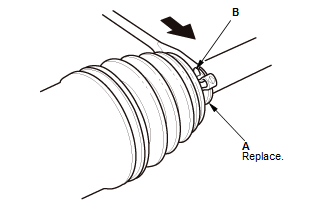
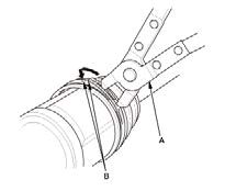
1. Boot Band - Remove
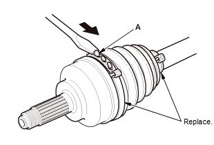
- Lift up the three tabs (A) using a flat-tipped screwdriver, then release the band.
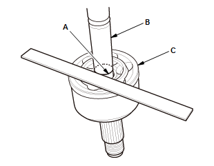
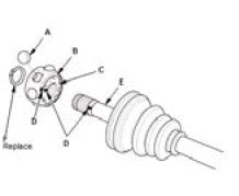
2. Inboard Joint - Remove
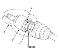
- Remove the snap ring (A)
- Make marks (B) on the bearing retainer (C) and the inboard joint (D) to identify the locations of the bearing retainer to the grooves in the inboard joint
- Remove the inboard joint on a clean shop towel (E). Be careful not to drop the steel balls when separating them from the inboard joint.
3. Bearing Retainer and Bearing Race - Remove
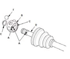
- Make marks (A) on the bearing retainer (B), the bearing race (C), and the driveshaft (D) to identify the position of the bearing retainer and the bearing race on the shaft
- Remove the circlip (E)
- Remove the bearing race and the steel balls (F).
NOTE: If necessary, use a commercially available bearing puller.
4. Inboard Boot - Remove
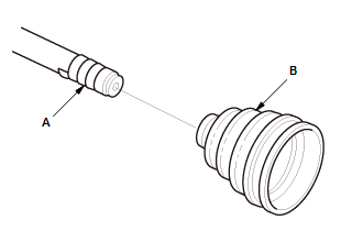
- Wrap the splines on the driveshaft with vinyl tape (A) to prevent damaging the inboard boot (B)
- Remove the inboard boot
- Remove the vinyl tape.
Outboard Joint
5. Boot Band - Remove
Ear clamp type
Low profile type
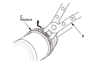
- Remove the boot bands:
- If the boot band is an ear clamp type (A), lift up the three tabs (B) using a flat-tipped screwdriver.
- If the boot band is a low profile type (C), pinch the boot band using commercially available CV boot clamp pliers (30500) (D).
6. Outboard Joint - Remove
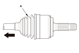
- Slide the outboard boot (A) partially toward the inboard joint side
- Wipe off the grease to expose the driveshaft and the outboard joint inner race.
- Make a mark (A) on the driveshaft (B) at the same level as the outboard joint end (C).
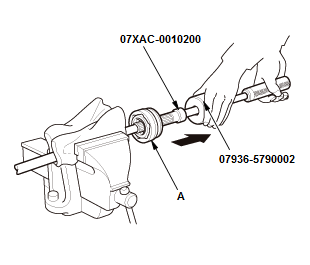
- Securely clamp the driveshaft in a bench vise with a shop towel wrapped around the driveshaft
- Remove the outboard joint (A) using the 24 x 1.5 mm threaded adapter and the sliding hammer set
- Remove the driveshaft from the bench vise.

- Remove the stop ring (A).
7. Outboard Boot - Remove
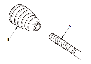
- Wrap the splines on the driveshaft with vinyl tape (A) to prevent damaging the outboard boot (B)
- Remove the outboard boot
- Remove the vinyl tape.
Reassembly
NOTE:
- Be careful not to damage the boot.
- Refer to the Exploded View as needed during this procedure.
Inboard Joint
1. Inboard Boot - Install
- Wrap the splines on the driveshaft with vinyl tape (A) to prevent damaging the inboard boot (B)
- Install new ear clamp bands (C) and the inboard boot (B) onto the driveshaft
- Remove the vinyl tape.
2. Bearing Retainer and Bearing Race - Install
- Assemble the steel balls (A), the bearing retainer (B), and the bearing race (C) by aligning the marks (D) you made on the bearing retainer and the bearing race
- Install the bearing onto the driveshaft (E) by aligning the marks you made on the bearing and the driveshaft. Be careful not to drop the steel balls when installing the bearing onto the driveshaft
- Install the circlip (F).
3. Inboard Joint - Install
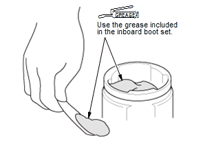
- Pack the inboard joint with the joint grease included in the new inboard boot set.
Grease quantity
Inboard joint: 80-100 g (2.82-3.52 oz)
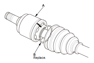
- Install the inboard joint onto the driveshaft by aligning the marks (A) you made on the inboard joint and the bearing retainer
- Install a new snap ring (B) into the inboard joint groove.
- Fit the boot ends (A) onto the driveshaft (B) and the inboard joint (C).
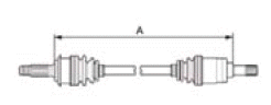
- Adjust the length (A) of the driveshafts in the figure as shown, then adjust the boots to halfway between full compression and full extension.
Left driveshaft 662.7-667.7 mm (26.090-26.287 in)
Right driveshaft 680.7-685.7 mm (26.799-26.996 in)
- Bleed excess air from the boots by inserting a flat-tipped screwdriver between the boot and the joint.
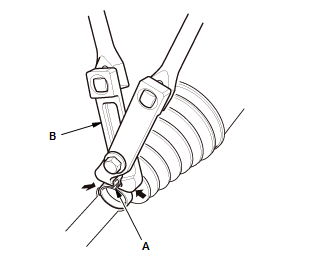
4. Boot Band - Install
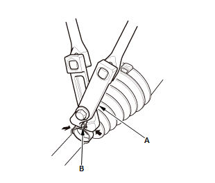
- Close the ear portion (A) of the band using a commercially available boot band clamp tool (Kent-Moore J-35910 or equivalent) (B).
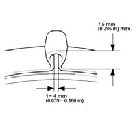
- Check the clearance between the closed ear portion of the band. If the clearance is not within the standard, close the ear portion of the band tighter.
- Repeat steps 2 and 3 for the band on the other end of the boot.
Outboard Joint
5. Outboard Boot - Install
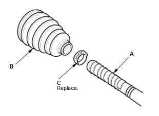
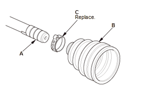
- Wrap the splines on the driveshaft with vinyl tape (A) to prevent damaging the outboard boot (B).
- Install a new ear clamp band (C) and the outboard boot onto the driveshaft.
- Remove the vinyl tape.
6. Outboard Joint - Install
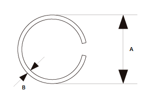
- Make sure to check the size of a new stop ring.

To avoid driveshaft and vehicle damage, make sure you install a new stop ring.
Stop ring specifications
Overall diameter (A): 23.5 mm (0.925 in)
Wire diameter (B): 1.6 mm (0.063 in)
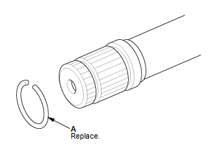
- Install the stop ring (A).
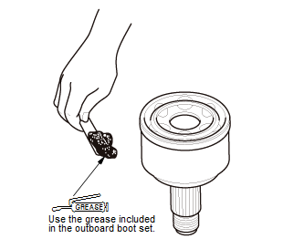
- Pack about 35 g (1.23 oz) of grease included in the new outboard boot
set
into the driveshaft hole in the outboard joint.
NOTE: If you are installing a new outboard joint, the grease is already installed.
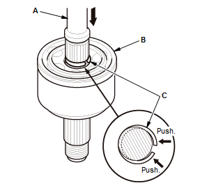
- Insert the driveshaft (A) into the outboard joint (B) until the stop ring (C) is close to the joint.
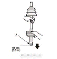
- To completely seat the outboard joint, pick up the driveshaft and the
joint, and
tap or hit the assembly onto a hard surface from a height of about 10 cm
(3.9 in).
NOTE: Do not use a hammer, as excessive force may damage the driveshaft. Be careful not to damage the threaded section (A) of the outboard joint.
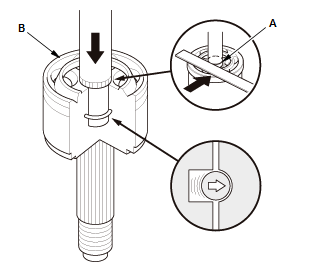
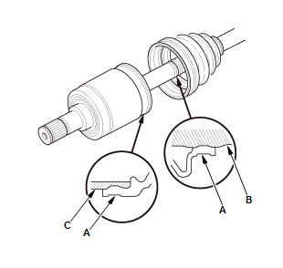
- Check the alignment of the paint mark (A) you made with the outboard joint end (B).
To avoid driveshaft and vehicle damage, the shaft must be all the way into the outboard joint to ensure the stop ring is properly seated.
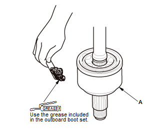
- Pack the outboard joint (A) with the remaining joint grease included in the outboard boot set.
Outboard joint: 55-75 g (1.94-2.65 oz)
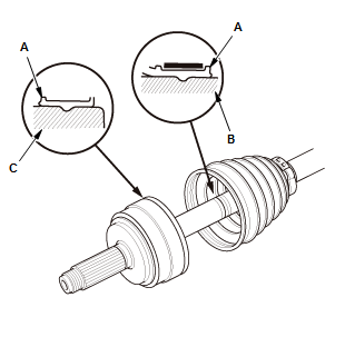
- Fit the boot ends (A) onto the driveshaft (B) and the outboard joint (C).
- Bleed any excess air from the boot by inserting a flat-tipped screwdriver between the boot and the joint.
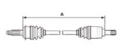
- Inspect the length (A) of the driveshafts in the figure as shown, then adjust the boots to halfway between full compression and full extension.
Left driveshaft 662.7-667.7 mm (26.090-26.287 in)
Right driveshaft 680.7-685.7 mm (26.799-26.996 in)
7. Boot Band - Install
- Close the ear portion (A) of the band using a commercially available boot band clamp tool (Kent-Moore J-35910 or equivalent) (B).
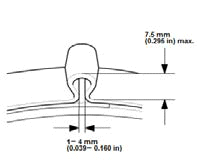
- Check the clearance between the closed ear portion of the band. If the clearance is not within the standard, close the ear portion of the band tighter.
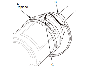
- Fit the boot ends onto the driveshaft and the inboard joint, then install a new low profile band (A) onto the boot (B)
- Hook the tab (C) of the band.
- Close the hook portion of the band using commercially available CV boot clamp pliers (30500) (A), then hook the tabs (B) of the band.
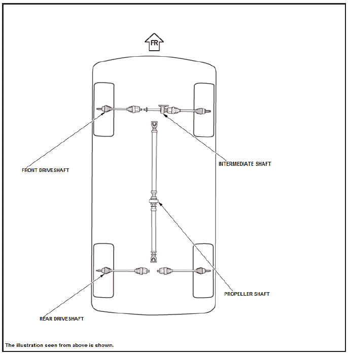
COMPONENT LOCATION INDEX
DRIVELINE/AXLE COMPONENT LOCATION INDEX
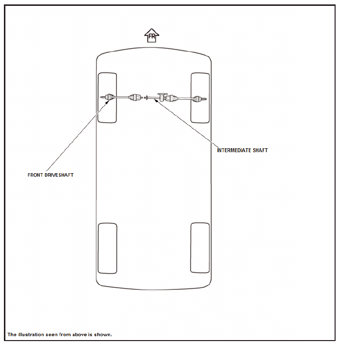
AWD
READ NEXT:
 Front Damper/Spring Removal and Installation
Removal & Installation
1. Vehicle - Lift
2. Front Wheel - Remove
3. Stabilizer Link - Disconnect
Disconnect the stabilizer link from the damper.
4. Damper/Spring Items - Remove
Fig. 1: Brake H
SEE MORE:
How to Troubleshoot the Lane Departure Warning (LDW)
LDW Indicator
When the LDW system is OK, the LDW indicator comes on for about 5 seconds
after turning the vehicle to the
ON mode, then it goes off.
When the LDW system detects a problem while operating, the LDW system stops
working, and the LDW
indicator (amber) stays on.
NOTE: The LDW system co
When You Cannot Open the Tailgate
■What to Do When Unable to Open the Tailgate
If you cannot open the tailgate, use the following procedure.
1. Wrap a cloth around the flat-tip
screwdriver. Put it into the cover as shown
in the image, and open it.
2. Wrap a cloth around the flat-tip
screwdriver. Put it into the lid as shown in
th
