Honda HR-V: Reassembly - CVT Transmission Disassembly and Reassembly (CVT)
NOTE:
- Refer to the Exploded View as needed during this procedure.
- Keep all foreign particles out of the transmission.
- When you reassemble the transmission, apply a light coat of clean transmission fluid on all oil seals, O-rings, and bearings. Also soak the forward clutch assembly and the reverse brake discs, in clean transmission fluid for at least 30 minutes prior to installation.
1. Reverse Brake Piston - Install
.png)
- Install the reverse brake piston (A) with new O-rings (B)
- Install the spring retainer/return spring (C).
.png)
- Put the reverse brake spring compressor attachment on the spring
retainer/return
spring assembly (A).
NOTE: Be sure the attachment is set over the return springs, not on the reverse brake piston (B)
- Install the reverse brake spring compressor plate (C) with facing the UP mark to the upside using bolts (D)
- Make sure that the reverse brake spring compressor bolt (E) is properly installed on the dent in the surface of the reverse brake spring compressor attachment (F)
- Compress the return springs using the reverse brake spring compressor until the snap ring securing the spring retainer/return spring can be installed
- Install a new snap ring (G).
NOTE:
- Be careful not to deform the snap ring by opening/closing it excessively.
- Make sure the snap ring is firmly installed in the groove.
- Remove the reverse brake spring compressor.
2. Reverse Brake Disc and Plate - Install
.png)
- Install the disc spring (A).
NOTE: Be sure to install the disc spring with the indented mark (B) facing the upward.
- Starting with the reverse brake plate (C), alternately install the reverse brake plates and the reverse brake discs (D).
- Install the reverse brake end-plate (E) with the flat side toward the top disc.
- Install a new snap ring (F).
NOTE:
- Be careful not to deform the snap ring by opening/closing it excessively.
- Make sure the snap ring is firmly installed in the groove.
3. Reverse Brake End-Plate Thrust Clearance - Inspect
- Set a dial indicator (A) on the reverse brake end-plate (B).
.png)
- Zero the dial indicator with the reverse brake end-plate is lifted up to the snap ring (C)
- Release the reverse brake end-plate
- Put the clutch compressor attachment and the clutch compressor attachment 64 mm on the reverse brake end-plate
- Press the clutch compressor attachment down with 39 N (4.0 kgf, 8.8 lbf) (the weight of the clutch compressor attachment is included) using a force gauge, and read the dial indicator
- The dial indicator reads the clearance (D) between the reverse brake end-plate and the top disc (E). Take measurements in at least three places, and use the average as the actual clearance.
Standard: 1.0-1.2 mm (0.039-0.047 in)
- If the clearance is out of the standard, remove the reverse brake end-plate and select a suitable one.
- 3.6 mm (0.142 in)
- 3.7 mm (0.146 in)
- 3.8 mm (0.150 in)
- 3.9 mm (0.154 in)
- 4.0 mm (0.157 in)
- 4.1 mm (0.161 in)
- 4.2 mm (0.165 in)
- 4.3 mm (0.169 in)
- 4.4 mm (0.173 in)
- 4.5 mm (0.177 in)
- 4.6 mm (0.181 in)
- 4.7 mm (0.185 in)
- 4.8 mm (0.189 in)
- 4.9 mm (0.193 in)
- 5.0 mm (0.197 in)
- Install a selected reverse brake end-plate, then recheck the clearance.
4. Sun Gear, Planetary Carrier, and Ring Gear - Install
.png)
- Install the ring gear (A), the thrust washer (B), and the collar (C) as shown
- Install the planetary carrier (D) and the thrust needle bearing (E) as shown
- Install the 33 x 40 mm thrust shim (F) and the sun gear (G)
- Install a new snap ring (H) using the snap ring pliers.
NOTE:
- Be careful not to deform the snap ring by opening/closing it excessively.
- Make sure the snap ring is firmly installed in the groove.
5. Sun Gear Thrust Clearance - Inspect
- Set a dial indicator (A) on the sun gear (B).
.png)
- Zero the dial indicator with the sun gear is lifted up to the 33 x 40 mm thrust shim (C) contact the snap ring (D)
- Release the sun gear
- Put the clutch compressor attachment on the sun gear
- Press the clutch compressor attachment down with 49 N (5.0 kgf, 11.0 lbf) (the weight of the clutch compressor attachment is included) using a force gauge, and read the dial indicator
- The dial indicator reads the clearance (E) between the sun gear and the 33 x 40 mm thrust shim. Take measurements in at least three places, and use the average as the actual clearance.
Standard: 0.04-0.09 mm (0.0016-0.0035 in)
- If the clearance is out of the standard, remove the 33 x 40 mm thrust shim and select a suitable one.
- 1.31 mm (0.0516 in)
- 1.34 mm (0.0528 in)
- 1.37 mm (0.0539 in)
- 1.40 mm (0.0551 in)
- 1.43 mm (0.0563 in)
- 1.46 mm (0.0575 in)
- 1.49 mm (0.0587 in)
- 1.52 mm (0.0598 in)
- 1.55 mm (0.0610 in)
- 1.58 mm (0.0622 in)
- 1.61 mm (0.0634 in)
- 1.64 mm (0.0646 in)
- 1.67 mm (0.0658 in)
- 1.70 mm (0.0669 in)
- 1.73 mm (0.0681 in)
- 1.76 mm (0.0693 in)
- 1.79 mm (0.0705 in)
- 1.82 mm (0.0717 in)
- 1.85 mm (0.0728 in)
- Install a selected 33 x 40 mm thrust shim, then recheck the clearance.
6. Stator Shaft and Input Shaft - Install
- Install new sealing rings (A).
.png)
- Check the needle bearing (B). If the needle bearing is worn or damaged, replace it
- Install the input shaft (C) by aligning the clutch discs (D) with the splines (E)
- Install a new sealing ring (F)
- Install the stator shaft (G) with the 26 x 38.8 mm thrust shim (H) and the thrust needle bearing (I) as shown.
7. Transmission Fluid Lubrication Pipe and Baffle Plate - Install
.png)
Fig. 40: Baffle Plate With Torque Specifications
- Install the transmission fluid lubrication pipe (A) by aligning the guide tab (B) with the guide hole (C)
- Install the baffle plate (D).
8. Oil Pump Drive Sprocket Sealing Ring - Install
.png)
- Install a new sealing ring (A).
9. Manual Valve Body and Stator Shaft Flange - Install
.png)
Fig. 41: Manual Valve Body and Stator Shaft Flange With Torque Specifications
- Install the stator shaft flange (A) with the dowel pins (B) (C) by aligning the transmission fluid lubrication pipe (D) and the dowel pins (B) with the mounting holes (E)
- Install the manual valve body (F) with the separator plate (G) and the dowel pins (H).
10. Control Shaft - Install
.png)
Fig. 42: Control Shaft With Torque Specifications
- Install the detent lever (A) by aligning the guide tab (B) with the groove (C).
- Install the control shaft (D)
- Install the roller (E) by aligning the mounting hole (F) with the groove (G)
- Secure the control shaft with a new lock washer (H), then pry up the lock tab (I) of the lock washer against the bolt head
- Install the detent spring (J).
11. Transmission Fluid Pump Drive Sprocket and Transmission Fluid Pump Drive Chain - Install
.png)
- Install the transmission fluid pump drive sprocket (A) and the transmission fluid pump drive chain (B)
- While expanding a new snap ring (C) of the transmission fluid pump drive
sprocket
using the snap ring pliers, install the transmission fluid pump drive
sprocket.
NOTE:
- Be careful not to deform the snap ring by opening/closing it excessively.
- Make sure the snap ring is firmly installed in the groove.
12. Final Drive Shaft and Differential Assembly - Install
.png)
- Install the final drive shaft assembly (A) and the differential assembly (B).
13. Torque Converter Housing - Install
.png)
- Remove all of the old liquid gasket from the mating surfaces of the transmission housing and the torque converter housing, the bolts, and the bolt holes
- Clean and dry the mating surfaces of the transmission housing and the torque converter housing
- Apply liquid gasket (Honda Genuine Liquid Gasket 5460H) to the
transmission
housing surface and to the inside edge of the threaded bolt holes. Install
the
component within 4 minutes of applying the liquid gasket.
NOTE:
- Apply a 1.5 mm (0.059 in) diameter bead of liquid gasket along the broken line (A) which is 3.9 mm (0.154 in) from the chamfering surface of the transmission housing inner side.
- Do not apply any liquid gasket to the bolt hole.
- Apply the liquid gasket all around as shown. When the bead is arriving at the end point, overlap the liquid gasket.
- The torque converter housing must be installed within 4 minutes. If too much time has passed after applying the liquid gasket, remove the old liquid gasket and residue, then reapply new liquid gasket.
- Do not touch the applied liquid gasket face.
.png)
Fig. 43: Torque Converter Housing With Torque Specifications (2WD)
.png)
Fig. 44: Torque Converter Housing With Torque Specifications (AWD)
- Install the torque converter housing (A) with the dowel pins (B), and
tighten the
bolts in a crisscross pattern in at least two steps.
NOTE:
- Wait for at least 1 hour before filling the transmission with transmission fluid.
- Do not run the engine for at least 3 hours after installing the torque converter housing.
14. Parking Brake Pawl - Install
.png)
Fig. 45: Parking Brake Pawl With Torque Specifications
- Install the parking brake rod holder (A) and a new lock washer (B)
- Pry up the lock tab (C) of the lock washer against the bolt head
- Install the parking brake pawl (D) with the parking shaft (E) and the parking pawl spring (F).
15. Transmission Fluid Pipe and Transmission Fluid Cooler Pipe - Install
.png)
Fig. 46: Transmission Fluid Pipe and Transmission Fluid Cooler Pipe With
Torque Specifications
- Install the transmission fluid pipes (A) with new O-rings (B)
- Install the transmission fluid cooler pipe (C).
16. End Cover - Install
.png)
- Install new sealing rings (A).
.png)
- Remove all of the old liquid gasket from the mating surfaces of the transmission housing and the end cover, the bolts, and the bolt holes
- Clean and dry the mating surfaces of the transmission housing and the end cover
- Apply liquid gasket (Honda Genuine Liquid Gasket 5460H) to the
transmission
housing surface and to the inside edge of the threaded bolt holes. Install
the
component within 4 minutes of applying the liquid gasket.
NOTE:
- Apply a 1.5 mm (0.059 in) diameter bead of liquid gasket along the broken line (A) which is 3.9 mm (0.154 in) from the chamfering surface of the end cover inner side.
- If too much time has passed after applying the liquid gasket, remove the old liquid gasket and residue, then reapply new liquid gasket.
- The end cover must be installed within 4 minutes. If too much time has passed after applying the liquid gasket, remove the old liquid gasket and residue, then reapply new liquid gasket.
- Do not touch the applied liquid gasket face.
.png)
Fig. 47: End Cover With Torque Specifications
- Install the end cover (A) with the dowel pins (B), and tighten the bolts
in a
crisscross pattern in at least two steps.
NOTE:
- Wait for at least 1 hour before filling the transmission with transmission fluid.
- Do not run the engine for at least 3 hours after installing the end cover.
17. Transmission Fluid Pump - Install
.png)
Fig. 48: Transmission Fluid Pump With Torque Specifications
- Install the transmission fluid pump (A) with the dowel pins (B).
18. Solenoid Wire Harness - Install
.png)
Fig. 49: Solenoid Wire Harness With Torque Specifications
- Connect the connectors (A).
- Install the transmission fluid temperature sensor (B)
- Install the ground terminals (C) and the harness clamps (D).
19. Valve Body Assembly - Install
.png)
- Install the transmission fluid pipes (A) with new O-rings (B).
- Install the solenoid wire harness subconnector (A) with a new O-ring (B).
.png)
Fig. 50: Valve Body Assembly With Torque Specifications
- Connect the connector (C)
- Install the valve body (D).
NOTE: Do not damage the solenoid wire harness (E) while installing the valve body assembly.
Length of Bolt
F - 90 mm (3.54 in)
G - 65 mm (2.56 in)
20. Transmission Fluid Pan and Transmission Fluid Strainer - Install
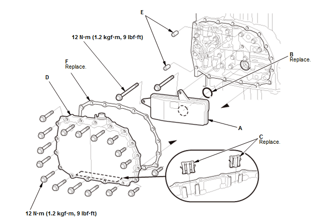
Fig. 51: Transmission Fluid Pan and Transmission Fluid Strainer With Torque
Specifications
- Install the transmission fluid strainer (A) with a new O-ring (B).
NOTE: Do not damage the solenoid wire harness while installing the transmission fluid strainer.
- Install new magnets (C)
- Install the transmission fluid pan (D) with the dowel pins (E) and a new
gasket (F), and tighten the bolts in a crisscross pattern in at least two
steps.
NOTE: Do not damage the solenoid wire harness while installing the transmission fluid pan.
21. Sensor - Install
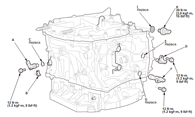
Fig. 52: Sensor With Torque Specifications
- Install the CVT speed sensor (A) with the sensor washer (B) and a new O-ring (C).
- Install the CVT drive pulley speed sensor (D) with a new O-ring (E)
- Install the torque converter turbine speed sensor (F) with a new O-ring (G)
- Install the CVT driven pulley pressure sensor (H) with a new sealing
washer (I).
NOTE: Be careful not to damage the plastic part.
22. Transmission Range Switch - Install
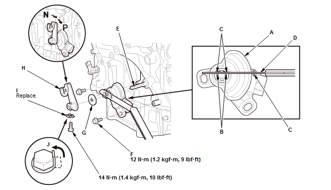
Fig. 53: Transmission Range Switch With Torque Specifications
- Set the transmission range switch (A) to the N position. Align the
cutouts (B) on the rotary-frame with the N positioning cutouts (C) on the
transmission range switch, then put a 2.0 mm
(0.079 in) feeler gauge (D) in the cutouts to hold the transmission range
switch in the N position.
NOTE: Be sure to use a 2.0 mm (0.079 in) feeler gauge or equivalent to hold the transmission range switch in the N position.
- Install the transmission range switch gently on the control shaft (E) while holding it in the N position with the 2.0 mm (0.079 in) feeler gauge
- Tighten the bolts (F) on the transmission range switch while you continue holding the N position
- Remove the feeler gauge
- Install the control shaft cover (G)
- Install the control lever (H) with a new lock washer (I)
- Pry up the lock tab (J) of the lock washer against the bolt head
- Turn the control lever to the P position.
23. Transfer Assembly - Install (With AWD)
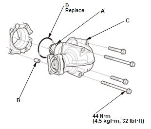
Fig. 54: Transfer Assembly With Torque Specifications
- Apply a light coat of clean transmission fluid to the transfer mount and transfer driven gear (A)
- Install the dowel pin (B)
- Install the transfer (C) with a new O-ring (D).
READ NEXT:
 Final Drive Shaft Disassembly and Reassembly (CVT)
Special Tools Required
Driver Handle, 15 x 135L 07749-0010000
Attachment, 45 mm 07947-6890300
Bearing Separator 07KAF-PS30200
Exploded View
1. Final Drive Shaft - Exploded View
Disassembly
NOTE: T
Shift Lever Disassembly and Reassembly (CVT)
Exploded View
1. Shift Lever Assembly - Exploded View
NOTE: Do not wipe off the special grease applied to the area of the shift
lever marked with an asterisk (*).
Fig. 55: Exploded View Of Shift Lev
Transfer Assembly Disassembly and Reassembly (CVT)
Special Tools Required
Oil Seal Driver Attachment, 58 mm 07JAD-PH80101
Holder, Companion 07PAB-0020000
Driver, 32.5 mm 070AD-SAA0100
Driver Handle, 15 x 135L 07749-0010000
Exploded View
1. Transfe
SEE MORE:
Description
AUTOMATIC DIMMING MIRRORS SYSTEM DESCRIPTION - CONTROL/FUNCTION
When the automatic dimming off button is turned ON, the control unit receives
signals from each sensor. Based
on the difference between the two lux levels (the light outside the vehicle and
the light from the headlights of
the other v
Front Brake Caliper Overhaul
Special Tools Required
Brake Caliper
Piston
Compressor
07AAE-SEPA101
Exploded View
1. Brake Caliper - Exploded View
Exploded View
Fig. 2: Brake Caliper Exploded View With Torque Specifications
Disassembly
Frequent inhalation of brake pad dust, regardless of material composition,
could be hazardo
