Honda HR-V: Starting System - Service Information
REMOVAL & INSTALLATION
ENGINE START/STOP SWITCH REMOVAL AND INSTALLATION
Removal and Installation
1. Dashboard switch Panel - Remove
2. Engine Start/Stop Switch - Remove
3. All Removed Parts - Install
- Install the parts in the reverse order of removal.
STARTER REMOVAL, INSTALLATION, AND PERFORMANCE TEST
Removal and Installation
1. 12 Volt Battery Terminal - Disconnect
2. Engine Undercover - Remove (With Engine Undercover)
3. Exhaust Pipe A - Remove
4. Intake Manifold Bracket - Remove
5. Connector (CKP Sensor) - Disconnect
6. Harness Holder - Remove
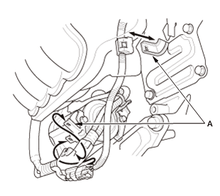
- Remove the harness holder clamps from the brackets (A).
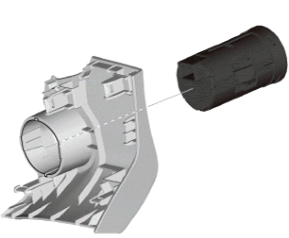
7. Starter - Remove
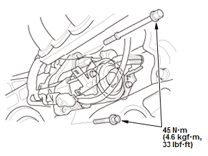
Fig. 1: Starter With Torque Specifications
- Remove the starter mounting bolts.
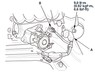
- Disconnect the positive cable (A) and the connector (B)
- Remove the Starter.
8. All Removed Parts - Install
- Install the parts in the reverse order of removal.
NOTE: Make sure the crimped side of the ring terminal faces away from the starter when you connect the positive cable.
Test
1. Starter Performance - Test
- Clamp the starter firmly in a vise
- Make the connections for this test using the thickest (gauge) wire possible (preferably the same gauge as used on the vehicle).
NOTE: To avoid damaging the starter, never leave the 12 volt battery connected for more than 5 seconds.
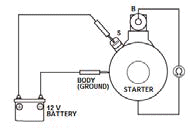
- Connect the 12 volt battery as shown, and check for continuity between the B terminal and the starter body. If there is continuity, it is working properly.
- Disconnect the 12 volt battery from the starter body, and check for continuity between the B terminal and the starter body. If there is no continuity, it is working properly.
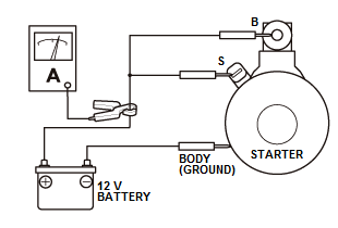
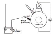
- Connect the starter to the 12 volt battery as shown, and confirm that the motor runs.
- If the electric current meets the specification when the 12 volt battery voltage is at 11.5 V, the starter is working properly.
Specification
Electric Current: 90 A or less
READ NEXT:
 Testing, Symptom Troubleshooting
TESTING
ENGINE START/STOP SWITCH TEST
Test
1. Dashboard switch Panel - Remove
2. Engine Start/Stop Switch - Test
Check the engine start/stop switch (A) according to the table.
NOTE:
When an
SEE MORE:
Locking/Unlocking the Doors from the Inside
■Using the Lock Tab
■ Locking a door
Push the lock tab forward.
■ Unlocking a door
Pull the lock tab rearward.
When you lock the door using the lock tab on the
driver's door, all the other doors and the tailgate lock
at the same time.
When you unlock the door using the lock tab on the
driver
Audio Remote Switch Removal and Installation
Removal & Installation
SRS components are located in this area. Review the SRS component locations -
Refer to: SRS Component
Location Index (KA/KC), or SRS Component Location Index (KA/KC) and the
precautions and
procedures before doing repairs or service.
1. Driver's Airbag - Remove
2. Lower
