Honda HR-V: DTC Troubleshooting B00DF-13: Open in the Front Passenger's Airbag ON/OFF Switch
NOTE:
- Before doing this troubleshooting procedure, find out if the vehicle was in a collision. If so, verify that all the required components were replaced with new components of the correct part number, and that they were properly installed.
- Before doing this troubleshooting procedure, review SRS Precautions and Procedures, General Troubleshooting Information, and 12 Volt Battery Terminal Disconnection and Reconnection.
- Before replacing the SRS unit, check the SRS unit software version with the HDS. If the software version is not the latest, update the SRS unit software, and retest.

1. Problem verification:
- Clear the DTCs with the HDS.
- Turn the vehicle to the ON mode, then wait for 10 seconds.
- Push and release the front passenger's airbag ON/OFF switch 5 times repeatedly.
- Check for DTCs with the HDS.

Is DTC B00DF-13 indicated?
YES
The failure is duplicated. Go to step 2.
NO
Intermittent failure, the system is OK at this time. Go to Troubleshooting Intermittent Failures. If another DTC is indicated, troubleshoot the DTC.
2. Front passenger's airbag ON/OFF switch check:
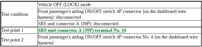
- Turn the vehicle to the OFF (LOCK) mode.
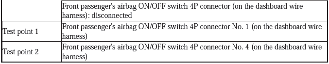
- Disconnect the following connector.
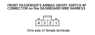
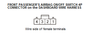
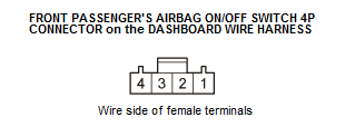
Front passenger's airbag ON/OFF switch 4P connector (on the dashboard wire harness)
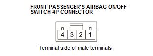
- Measure the resistance between the front passenger's airbag ON/OFF switch 4P connector terminals No. 1 and No. 4 according to the table.
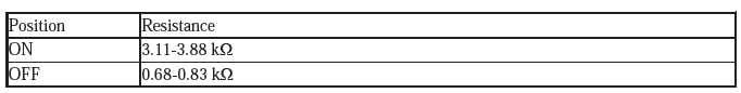
Is the resistance as specified?
YES
Go to step 3.
NO
Faulty front passenger's airbag ON/OFF switch or poor connection at front passenger's airbag ON/OFF switch 4P connector and the front passenger's airbag ON/OFF switch. Check the connection; if the connection is OK, replace the front passenger's airbag ON/OFF switch - Refer to: Front Passenger's Airbag ON/OFF Switch Removal and Installation, or Front Passenger's Airbag ON/OFF Indicator Removal and Installation, then clear the DTC.
3. Shorted wire check (ACS, GND lines to power):
- Turn the vehicle to the ON mode.
- Measure the voltage between test points 1 and 2.

Is there 0.2 V or less?
YES
The ACS and GND wires are not shorted to power. Go to step 4.
NO
Short to power in the dashboard wire harness; replace the dashboard wire harness, then clear the DTC.
4. Open wire check (ACS line):
- Turn the vehicle to the OFF (LOCK) mode.
- Disconnect the negative cable from the 12 volt battery, then wait at least 3 minutes.
- Disconnect the following connector.
SRS unit connector A (39P)
- Measure the resistance between test points 1 and 2.
Is there 1.0 Ω or less?
YES
The ACS wire is OK. Go to step 5.
NO
Open in the dashboard wire harness; replace the dashboard wire harness, then clear the DTC.
5. Open wire check (GND line):
Measure the resistance between test points 1 and 2.

Is there 1.0 Ω or less?
YES
The GND wire is OK. Replace the SRS unit.
NO
Open in the dashboard wire harness; check for a poor ground at G403. If the ground is OK, replace the dashboard wire harness, then clear the DTC.
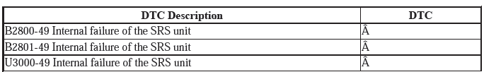
DTC TROUBLESHOOTING B2800-49, B2801-49, U3000-49: INTERNAL FAILURE OF THE SRS UNIT
NOTE:
- Before doing this troubleshooting procedure, find out if the vehicle was in a collision. If so, verify that all the required components were replaced with new components of the correct part number, and that they were properly installed.
- Before troubleshooting any of these DTCs, check the 12 volt battery/system voltage and 12 volt battery cable connections. If the voltage is low, repair the charging system, test and charge the 12 volt battery, or replace the 12 volt battery before troubleshooting the SRS. If the 12 volt battery/system voltage is OK, ask the customer if the 12 volt battery ever went dead or if the engine was started and run with the 12 volt battery in a low state of charge. A dead 12 volt battery may trigger one or more of these DTCs.
- Before doing this troubleshooting procedure, review SRS Precautions and Procedures and General Troubleshooting Information.
- Before replacing the SRS unit, check the SRS unit software version with the HDS. If the software version is not the latest, update the SRS unit software, and retest.
1. Problem verification:
- Clear the DTCs with the HDS.
- Turn the vehicle to the ON mode, then wait for 10 seconds.
- Check for DTCs with the HDS.
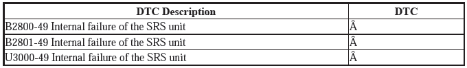
Is DTC B2800-49, B2801-49, or U3000-49 indicated?
YES
The failure is duplicated. Replace the SRS unit.
NO
Intermittent failure, the system is OK at this time. Go to Troubleshooting Intermittent Failures. If another DTC is indicated, troubleshoot the DTC.
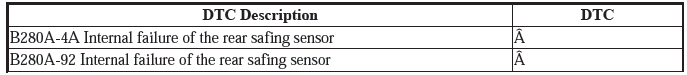
DTC TROUBLESHOOTING B280A-4A, B280A-92: INTERNAL FAILURE OF THE REAR SAFING SENSOR
NOTE:
- Before doing this troubleshooting procedure, find out if the vehicle was in a collision. If so, verify that all the required components were replaced with new components, of the correct part number, and that they were properly installed.
- Before doing this troubleshooting procedure, review SRS Precautions and Procedures and General Troubleshooting Information.
- Before replacing the SRS unit, check the SRS unit software version with the HDS. If the software version is not the latest, update the SRS unit software, and retest.
1. Problem verification:
- Clear the DTCs with the HDS.
- Turn the vehicle to the ON mode, then wait for 10 seconds.
- Check for DTCs with the HDS.
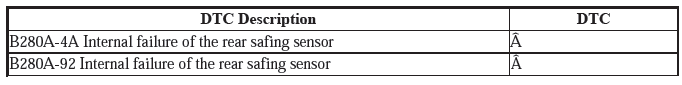
Is DTC B280A-4A or B280A-92 indicated?
YES
The failure is duplicated. Replace the rear safing sensor, then clear the DTC, and retest. If the DTC is still present, replace the SRS unit.
NO
Intermittent failure, the system is OK at this time. Go to Troubleshooting Intermittent Failures. If another DTC is indicated, troubleshoot the DTC.
READ NEXT:
 DTC Troubleshooting B280A-87: No Signal From the Rear Safing Sensor
NOTE:
Before doing this troubleshooting procedure, find out if the vehicle was
in a collision. If so, verify
that all the required components were replaced with new components, of the
correct p
DTC Troubleshooting B2840-13, B2841-13: SRS Unit Connector Not
Properly Installed
NOTE:
Before doing this troubleshooting procedure, find out if the vehicle was
in a collision. If so, verify
that all the required components were replaced with new components of the
correct pa
DTC Troubleshooting U0101-00: Lost Communication with the PCM (SRS
Unit)
NOTE:
Before doing this troubleshooting procedure, find out if the vehicle was
in a collision. If so, verify
that all the required components were replaced with new components of the
correct pa
SEE MORE:
Maintenance Service Reminder
NOTE: To determine the appropriate reset procedure, refer to MAINTENANCE
SERVICE
REMINDER RESET INDEX.
MAINTENANCE REQUIRED REMINDER LIGHT RESET INDEX
MAINTENANCE SERVICE REMINDER RESET - PROCEDURE 1
1. At each 7500 mile service interval, the MAINTENANCE REQUIRED light will
change from Green to
Y
Interior Lighting - Service Information
REMOVAL & INSTALLATION
CARGO AREA LIGHT REMOVAL, INSTALLATION, AND TEST
Removal & Installation
1. Cargo Area Light - Remove
Carefully pry off the cargo area light (A) to the side to release the
hook and pull out the light
Disconnect the connector (B)
Remove the bulb (C) from the cargo
