Honda HR-V: Engine Oil Pan Removal and Installation
Removal
1. Right Front Wheel - Remove
2. Front Splash Shield and Engine Undercover (With Engine Undercover) - Remove
3. Drive Belt - Remove
4. A/C Compressor - Move
NOTE:
- Do not disconnect the A/C hoses.
- Do not bend the A/C hoses excessively.
- Disconnect the connector at the same time.
- Hang the A/C compressor with a wire tie.
5. Engine Oil - Drain
6. A/C Compressor Bracket - Remove
.png)
7. Exhaust Pipe A - Remove
8. Intermediate Shaft Mounting Bolt - Remove
9. Engine - Support
- Support the transmission with a transmission jack and a wood block under the transmission.
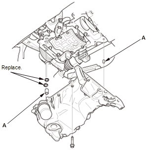
10. Torque Rod and Torque Rod Bracket - Remove
11. CKP Sensor Cover - Remove
12. Oil Pan - Remove
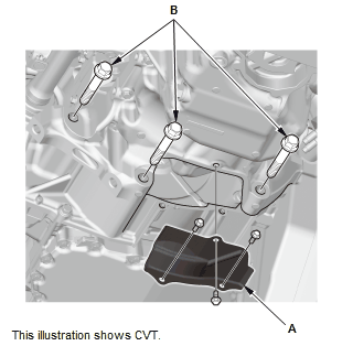
1. Remove the clutch case cover (M/T) or the torque converter cover (CVT) (A) and the transmission mounting bolts (B).
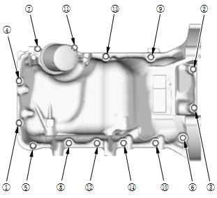
Fig. 17: Oil Pan Removal Sequence
2. Remove the bolts securing the oil pan.
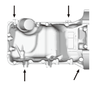
3. Using a flat blade screwdriver, separate the oil pan from the lower block in the places shown.
4. Remove the oil pan.
Installation
1. Oil Pan - Install
- Apply liquid gasket to the lower block and the oil pump mating surface of the oil pan, and to the inside edge of the threaded bolt holes.
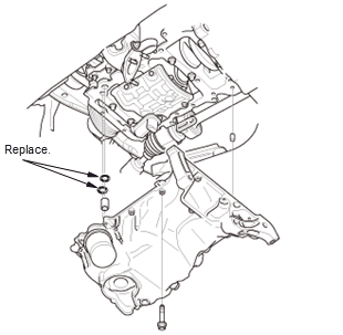
- Install the dowel pins (A).
- Loosely install the oil pan with new O-rings.
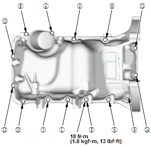
Fig. 18: Oil Pan Tightening Sequence
- Tighten the bolts in three steps; tighten the bolts until the bolts sit on the oil pan, tighten the bolts until the gasket is compressed, tighten the bolts to specified torque. Wipe off the excess liquid gasket on the crankshaft pulley and the flywheel (M/T) or the drive plate (CVT).
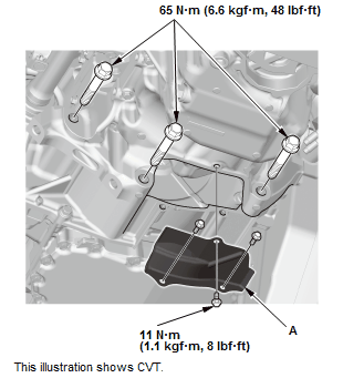
Fig. 19: Clutch Case Cover With Torque Specifications
- Install the clutch case cover (M/T) or the torque converter cover (CVT) (A) and the transmission mounting bolts.
2. CKP Sensor Cover - Install
3. Torque Rod Bracket and Torque Rod - Install
4. Transmission Jack and Wood Block - Remove
5. Intermediate Shaft Mounting Bolt - Install
6. Exhaust Pipe A - Install
7. A/C Compressor Bracket - Install
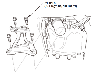
Fig. 20: AC Compressor Bracket With Torque Specifications
8. A/C Compressor - Install
NOTE: Connect the connector at the same time.
9. Drive Belt - Install
10. Front Splash Shield and Engine Undercover (With Engine Undercover) - Install
11. Right Front Wheel - Install
12. Engine Oil - Refill
READ NEXT:
 Engine Oil Pump Removal and Installation
Removal
1. Right Front Wheel - Remove
2. Front Splash Shield and Engine Undercover (With Engine Undercover) -
Remove
3. Drive Belt Auto-Tensioner - Remove
4. Drive Belt Idler Pulley Base - Remove
5.
Engine Removal and Installation
Special Tools Required
Universal Lifting
Eyelet 07AAKSNAA120
Removal
NOTE:
Use fender covers to avoid damaging painted surfaces.
To avoid damaging the wiring and terminals, unplug the wiring conne
FTP Sensor Removal and Installation (KA/KC)
Removal & Installation
1. EVAP Canister Assembly - Remove - Refer to: EVAP Canister Removal and
Installation (AWD), or
EVAP Canister Removal and Installation (KA/KC)
2. FTP Senor - Remove
Disc
SEE MORE:
CVT Differential Backlash Inspection (CVT)
Inspection
1. Differential Backlash - Inspect
Install both axles into the differential, then place the axles on
V-blocks (A)
Check the backlash of the pinion gears (B) using a dial indicator (C).
Standard: 0.05-0.15 mm (0.0020-0.0059 in)
If the backlash is out of the standard, replace the d
SRS Symptom Troubleshooting - Front Passenger's Airbag ON/OFF Switch
To ON, But Front Passenger's Airbag ON Indicator Does Not Come ON
NOTE:
Before doing this troubleshooting procedure, find out if the vehicle was
in a collision. If so, verify that all the required components were replaced
with new components of the correct part
number, and that they were properly installed.
Before doing this troubleshooting procedure, revi
