Honda HR-V: Mainshaft Disassembly, Reassembly, and Inspection (M/T)
Special Tools Required
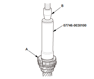
Driver Handle, 40 mm I.D. 07746-0030100
.png)
Driver, 30 mm I.D. 07946-MB00000
.png)
Disassembly
NOTE: Refer to the Exploded View as needed during this procedure.
1. Mainshaft - Disassemble
.png)
- Support 6th gear (A) on steel blocks, and press the mainshaft out of the
angular ball
bearing (B) and 6th gear using an attachment (C) and a press (D).
NOTE: Do not use a jaw-type puller; it can damage the gear teeth.
.png)
- Support 5th gear (A) on steel blocks, and press the mainshaft out of the
5th/6th
synchro hub (B) and 5th gear using an attachment (C) and a press (D).
NOTE: Do not use a jaw-type puller; it can damage the gear teeth.
.png)
- Support 3rd gear (A) on steel blocks, and press the mainshaft out of the
3rd/4th
synchro hub (B) and 3rd gear using an attachment (C) and a press (D).
NOTE: Do not use a jaw-type puller; it can damage the gear teeth.
.png)
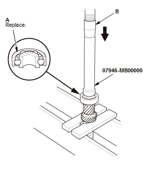
- Support the angular ball bearing (A) on steel blocks, and press out the mainshaft using an attachment (B) and a press (C).
Inspection
1. Mainshaft - Inspect
Standard:
- Ball Bearing Contact Area (Transmission Housing Side): 30.984-31.000 mm (1.21984-1.22047 in)
- 6th Gear Distance Collar Contact Area: 32.984-33.000 mm (1.29858-1.29921 in)
- 4th/5th Gear Distance Collar Contact Area: 35.984-36.000 mm (1.41669-1.41732 in)
- Needle Bearing Contact Area: 41.984-42.000 mm (1.65291-1.65354 in)
- Ball Bearing Contact Area (Clutch Housing Side):
28.002-28.015 mm (1.10244-1.10295 in)
Crankshaft Pilot Bushing Contact Area: 20.80-20.85 mm (0.8189-0.8209 in)
Service Limit:
- 30.984 mm (1.21984 in)
- 32.984 mm (1.29858 in)
- 35.984 mm (1.41669 in)
- 41.984 mm (1.65291 in)
- 28.002 mm (1.10244 in)
- 20.80 mm (0.8189 in)
.png)
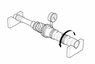
- Inspect the runout by supporting both ends of the mainshaft. Then rotate the mainshaft two complete turns while measuring with a dial gauge. If the runout exceeds the standard, replace the mainshaft.
Standard: 0.02 mm max.
Exploded View
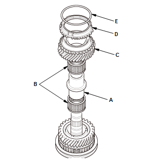
1. Mainshaft - Exploded View
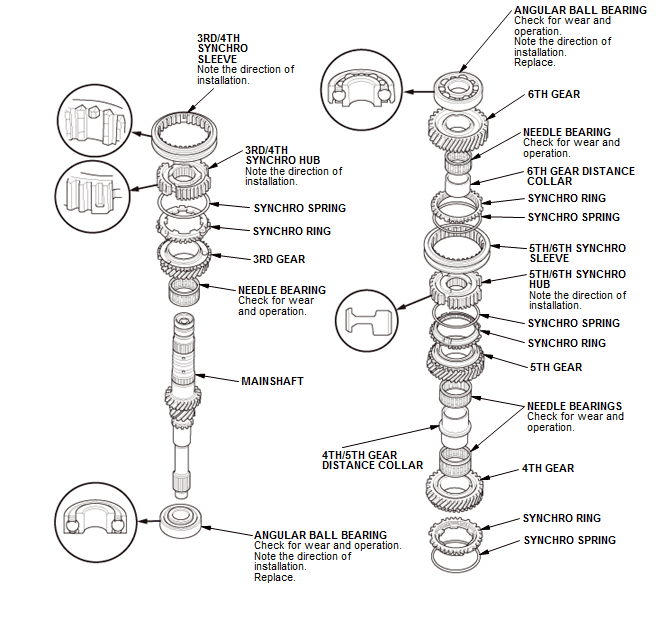
Fig. 28: Exploded View Of Mainshaft
Reassembly
NOTE: Refer to the Exploded View as needed during this procedure.
1. Mainshaft - Reassemble
- Clean all parts in solvent, dry them, and apply MTF to all contact surfaces
- Press in a new angular ball bearing (A) using the 30 mm I.D. driver and
a press (B).
NOTE: Check the ball bearing install direction.
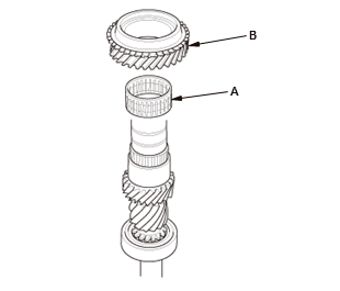
- Install the needle bearing (A)
- Install 3rd gear (B).

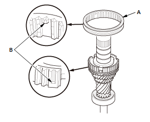
- Install the synchro ring (A) and synchro spring (B).
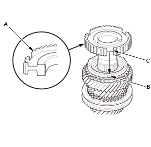
- Install the 3rd/4th synchro hub (A) by aligning the synchro ring fingers
(B) with the
grooves (C) in the 3rd/4th synchro hub.
NOTE: Make sure to install the 3rd/4th synchro hub in the direction shown.
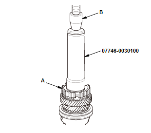
- Press on the 3rd/4th synchro hub (A) using the 40 mm I.D. driver handle and a press (B).
- Install the 3rd/4th synchro sleeve (A) by aligning the stops (B) of the 3rd/4th synchro sleeve and the 3rd/4th synchro hub
- Check the operation of the 3rd/4th synchro hub set.
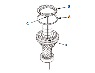
- Install the synchro spring (A)
- Install the synchro ring (B) by aligning the synchro ring fingers (C) with the grooves in 3rd/4th synchro hub (D).
- Install the 4th gear (A).
- Install the 4th/5th gear distance collar (A) with the needle bearings (B) and 5th gear (C)
- Install the synchro ring (D) with the synchro spring (E) onto 5th gear.
- Install the 5th/6th synchro hub (A) by aligning the synchro ring fingers (B) with the grooves (C) in the 5th/6th synchro hub.
- Press on the 5th/6th synchro hub (A) using the 40 mm I.D. driver handle and a press (B).
- Install the 5th/6th synchro sleeve (A) by aligning the slots of the
5th/6th synchro
sleeve and the 5th/6th synchro hub (B).
NOTE: Make sure to align the slots in the 5th/6th synchro sleeve as shown.
- Check the operation of the 5th/6th synchro hub set.
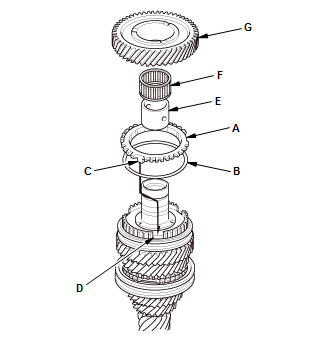
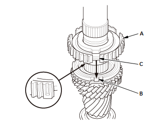
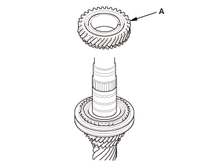
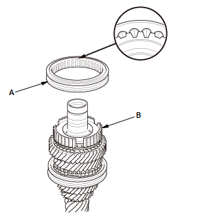
- Install the synchro ring (A) with the synchro spring (B) by aligning the synchro ring fingers (C) with the grooves (D) in the 5th/6th synchro hub
- Install the 6th gear distance collar (E) with the needle bearing (F) and 6th gear (G).
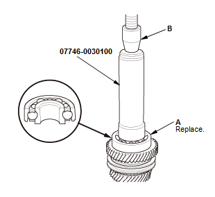
- Press on a new angular ball bearing (A) using the 40 mm I.D. driver
handle and a
press (B).
NOTE: Check the ball bearing install direction.
READ NEXT:
 Synchro Sleeve and Hub Disassembly, Reassembly, and Inspection (M/T)
Inspection
1. Synchro Sleeve and Hub - Inspect
Inspect the gear teeth on all synchro hubs and synchro sleeves for wear
(rounded off
corners)
Install each synchro hub (A) in its mating synchro s
SEE MORE:
How to Troubleshoot the Audio System
NOTE: Refer to How to Troubleshoot the Navigation System for information
about the audio-navigation unit.
How to Recognize Audio unit and Audio-Navigation Unit (Display Audio Type
(7-Inch Screen) )
There are two kinds of 7-inch display audio units depending on vehicle model.
These units exist as
Symptom Troubleshooting
CVT SYMPTOM TROUBLESHOOTING INDEX (CVT)
NOTE: Do an all DTC check with the HDS, and troubleshoot any DTCs first
before following the repair procedures listed in the index.
CIRCUIT DIAGRAM
CVT ELECTRONIC CONTROL SYSTEM CIRCUIT DIAGRAM (CVT)
Fig. 27: CVT Electronic Control System Circuit Dia
