Honda HR-V: Front Driveshaft Disassembly and Reassembly
Special Tools Required
CV Boot Clamp Pliers 30500, commercially available
.png)
Bearing Puller, commercially available
.png)
Slide Hammer 5/8"-18 UNF, commercially available
.png)
Threaded Adapter, 26 x 1.5 mm 07XAC-001030A
.png)
Boot Band Clamp Tool Kent-Moore J-35910 or equivalent, commercially available
.png)
Exploded View
1. Driveshaft - Exploded View
.png)
Fig. 1: Exploded View Of Driveshaft
Disassembly
NOTE: Be careful not to damage the boot.
Inboard Joint
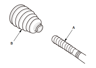
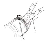
1. Boot Band - Remove
Low profile type
.png)
Ear clamp type
.png)
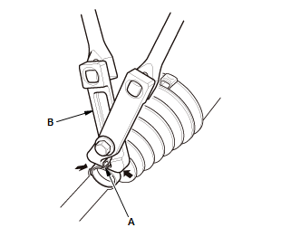
- Remove the boot bands:
- If the boot band is a low profile type (A), pinch the boot band using CV boot clamp pliers (30500) (B).
- If the boot band is an ear clamp type (C), lift up the three tabs (D) using a flat-tipped screwdriver.
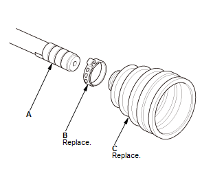
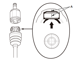
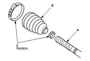
2. Inboard Boot Adapter - Remove
.png)
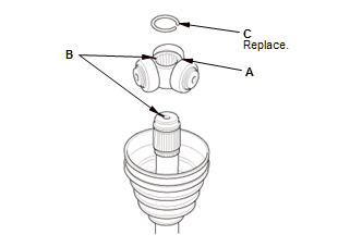
- Make marks (A) on each roller (B) and the inboard joint (C) to identify
the
locations of the rollers to the grooves in the inboard joint.
NOTE: Do not engrave or scribe any marks on the rolling surface.
- Remove the inboard joint on a clean shop towel (D).
.png)
- Remove the inboard boot adapter (A).
3. Spider - Remove
.png)
- Remove the circlip (A)
- Make marks (B) on the spider (C) and the driveshaft (D) to identify the position of the shaft
- Remove the spider.
NOTE: If necessary, use a commercially available bearing puller while being careful not to damage the spider.
4. Inboard Boot - Remove
.png)
- Wrap the splines on the driveshaft with vinyl tape (A) to prevent damaging the inboard boot (B).
- Remove the inboard boot.
- Remove the vinyl tape.
Outboard Joint
5. Boot Band - Remove
.png)
- Lift up the three tabs (A) using a flat-tipped screwdriver, then release the band.
6. Outboard Joint - Remove
.png)
- Slide the outboard boot (A) partially toward the inboard joint side.
- Wipe off the grease to expose the driveshaft and the outboard joint inner race.
.png)
- Make a mark (A) on the driveshaft (B) at the same level as the outboard joint end (C).
.png)
- Securely clamp the driveshaft in a bench vise with a shop towel wrapped around the driveshaft.
- Remove the outboard joint (A) using the 26 x 1.5 mm threaded adapter and the sliding hammer set.
- Remove the driveshaft from the bench vise.
.png)
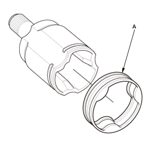
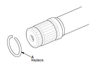
- Remove the stop ring (A).
7. Outboard Boot - Remove
- Wrap the splines on the driveshaft with vinyl tape (A) to prevent damaging the outboard boot (B).
- Remove the outboard boot
- Remove the vinyl tape.
Reassembly
NOTE:
- Be careful not to damage the boot.
- Refer to the Exploded View as needed during this procedure.
Inboard Joint
1. Inboard Boot - Install
- Wrap the splines on the driveshaft with vinyl tape (A) to prevent damaging the inboard boot.
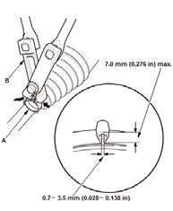
- install a new ear clamp band (B) and a new inboard boot (C) onto
the driveshaft.
NOTE: Do not reuse the removed inboard boot.
- Remove the vinyl tape.
2. Spider - Install
- Install the spider (A) onto the driveshaft by aligning the marks (B) you made on the spider and the end of the driveshaft.
- Install a new circlip (C)
- Always rotate the circlip in its groove to make sure it is fully seated.
3. Inboard Boot Adapter - Install
- Install the inboard boot adapter (A).
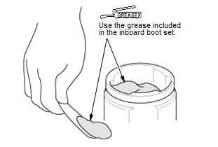
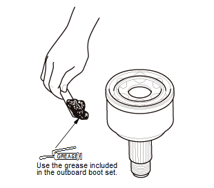
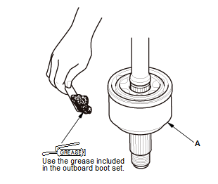
- Pack the inboard joint with the joint grease included in the new inboard boot set.
- Fit the inboard joint onto the driveshaft.
NOTE: Reinstall the inboard joint onto the driveshaft by aligning the marks (A) you made on the inboard joint and the rollers.
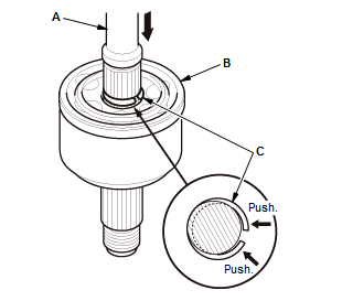
- Fit the boot ends (A) onto the driveshaft (B) and the inboard boot adapter (C).
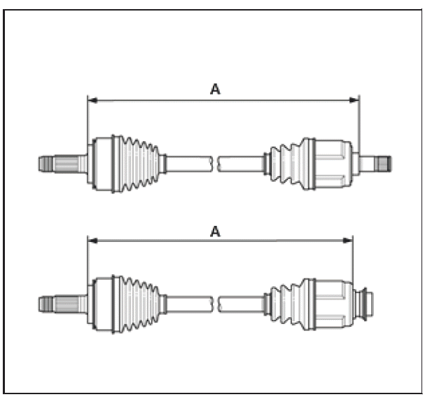
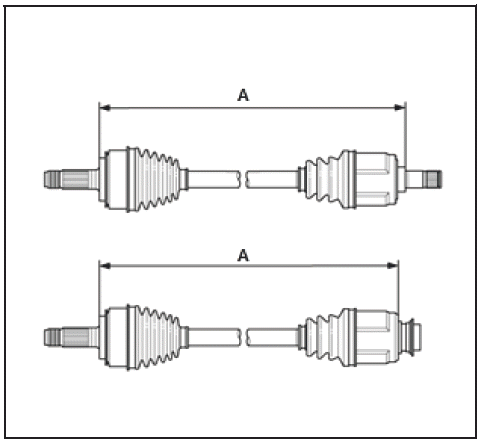
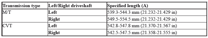
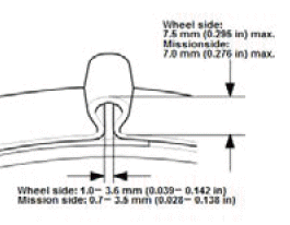
- Adjust the length (A) of the driveshafts in the figure as shown, then adjust the boots to halfway between full compression and full extension.

- Bleed excess air from the boots by inserting a flat-tipped screwdriver between the boot and the joint.
4. Boot Band - Install
- Install new boot bands:
- For the ear clamp type, go to step 2.
- For low profile type, go to step 4.
- Close the ear portion (A) of the band using a commercially available boot band clamp tool (Kent-Moore J-35910 or equivalent) (B)
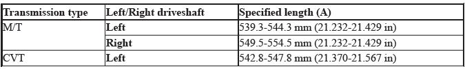
- Check the clearance between the closed ear portion of the band. If the clearance is not within the standard, close the ear portion of the band tighter.
- Fit the boot ends onto the driveshaft and the inboard joint, then install a new low profile band (A) onto the boot (B)
- Hook the tab (C) of the band.
- Close the hook portion of the band using commercially available CV boot clamp pliers (30500) (A), then hook the tabs (B) of the band.
Outboard Joint
5. Outboard Boot - Install
- Wrap the splines on the driveshaft with vinyl tape (A) to prevent damaging the outboard boot (B)
- Install new ear clamp bands (C) and the outboard boot onto the driveshaft
- Remove the vinyl tape.
6. Outboard Joint - Install
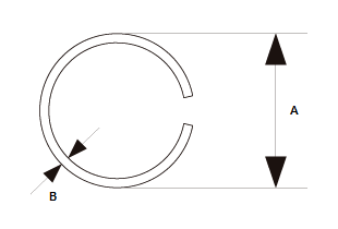
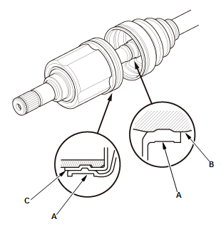
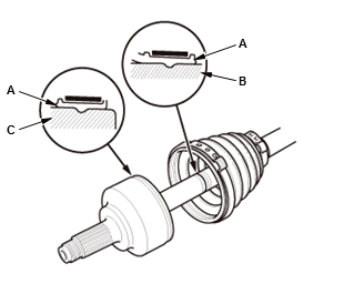
- Make sure to check the size of a new stop ring.

To avoid driveshaft and vehicle damage, make sure you install a new stop ring.
Stop ring specifications
Overall diameter (A): 24.9 mm (0.980 in)
Wire diameter (B): 2.0 mm (0.079 in)
- Install the stop ring (A).
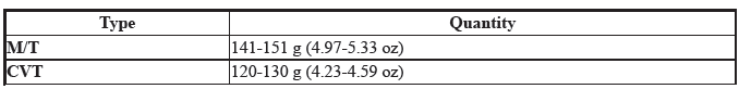
- Pack about 35 g (1.23 oz) of grease included in the new outboard boot
set
into the driveshaft hole in the outboard joint.
NOTE: If you are installing a new outboard joint, the grease is already installed.
- Insert the driveshaft (A) into the outboard joint (B) until the stop ring (C) is close to the joint.
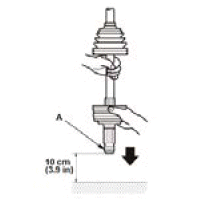
- To completely seat the outboard joint, pick up the driveshaft and the
joint, and
tap or hit the assembly onto a hard surface from a height of about 10 cm
(3.9 in).
NOTE: Do not use a hammer, as excessive force may damage the driveshaft. Be careful not to damage the threaded section (A) of the outboard joint.
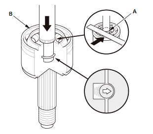
- Check the alignment of the paint mark (A) you made with the outboard joint end (B).
To avoid driveshaft and vehicle damage, the shaft must be all the way into the outboard joint to ensure the stop ring is properly seated.
- Pack the outboard joint (A) with the remaining joint grease included in the outboard boot set.
Total grease quantity
Outboard joint: 110-130 g (3.88-4.59 oz)
- Fit the boot ends (A) onto the driveshaft (B) and the outboard joint (C)
- Bleed any excess air from the boot by inserting a flat-tipped screwdriver between the boot and the joint.
- Inspect the length (A) of the driveshafts in the figure as shown, then adjust the boots to halfway between full compression and full extension.
7. Boot Band - Install
- Close the ear portion (A) of the band using a commercially available boot band clamp tool (Kent-Moore J-35910 or equivalent) (B).
- Check the clearance between the closed ear portion of the band. If the clearance is not within the standard, close the ear portion of the band tighter
- Repeat steps 1 and 2 for the band on the other end of the boot.
READ NEXT:
 Intermediate Shaft Disassembly and Reassembly
Special Tools Required
Half Shaft Base 07NAF-SR30101
Oil Seal Driver, 44.5 mm 07947-SB00100
Driver Handle, 15 x 135L 07749-0010000
Bearing Driver Attachment, 52 x 55 mm
07746-0010400
Oil Seal Driv
Rear Driveshaft Disassembly and Reassembly (AWD)
Special Tools Required
Slide Hammer 5/8"-18 UNF, commercially available
Threaded Adapter, 22 x 1.5 mm 07XAC-001010A
Boot Band Clamp Tool Kent-Moore J-35910 or
equivalent, commercially available
CV
SEE MORE:
Rear Seat-Back Disassembly And Reassembly
Disassembly & Reassembly
1. Rear Seat-Back - Remove
2. Rear Seat-Back Latch - Remove
3. Rear Seat Armrest - Remove
4. Rear Seat-Back Pad/Frame - Remove
Remove the tether anchor cover (A) with a flat-tip screwdriver. (for
some
models).
NOTE : The illustration shows a left rear seat. Do the
Crankshaft Main Bearing Replacement
Replacement
1. Engine/Transmission - Remove
2. Transmission - Remove
Remove the transmission:
M/T
CVT
3. Pressure Plate, Clutch Disc, and Flywheel - Remove (M/T)
4. Drive Plate - Remove (CVT)
5. Cylinder Head - Remove
6. Lower Block and Bearing Half - Remove
NOTE: Do not remove the connec
